
I'm on IRF630's now as a trial. If we have the need for 100ns switching or total time of pulse to draw aether energies, then MOSFET's are the way to go it would seem. IRF630's aren't that good, but i've found at least 1 or 2 on each old monitor circuit board (200V 9A).
Pulse motors run with them from 4V in my tests and the only difference to transistors being a 1K resistor on the Gate leg. Similar amp draw of just 8mA at 4V on a simple switcher circuit with a Hall.
-
speed
Originally posted by Joit View Post
Yes speed is every thing.
The main primary function in this work is we are making DC pulse motors.
The one underlying function of all the OU devices that work with coils and neo magnets is instantaneous transition time from power on to power off. It is not acceptable to have any propagation delays. Some say you need to employ mechanical switching for the best possible speed like to old style point in your cars ignition system. Just too hard to control
and have a very short life span. With the advances in Hex FET and BiCMOS technology
we should be able to achieve some good results.
In electronics we call this the slew rate and all devices have a rated slew rate that they are expected to switch at.
In the photo below.

The variation between the red line and the green line is the delay time from off to on
Volts rise time per micro second.
I believe that the real OU will be available with hi speed switching at voltage ranges in 1000 volts and going up. I already have recorded data that shows more efficiency with higher voltages. And better COP using the same coils just high voltages. This is where I am slowly developing my electronics.
I have been buying up semiconductors from all over the world that have voltage ratings in the KVA range. With the death of the cathode ray tube all the big high transistors are going out cheap. So get them while you can.
Anyway that's what I am working towards.
maybe it will all go up in smoke like the FETS do lol
Leave a comment:
-
Maybe that is the trick at the Mosfets.
When i pulse an NPN like the 3055 i got Way lower Spikes as with a IRF540 or higher.
The NPN want to switch a bigger Amount of Energy reliable,
but when you use a Mosfet for a low Amount of Watts, like a Pulse creates,
the Mosfet can transform the Current better into Voltage.
Seems its the Base, what is faster saturated, even a Mosfet behaves more like a unpoled Capacitor regarding Base and Drain.Leave a comment:
-
Thanks toranarod Yes, MJL's need about .25A to stay in the right part of their curve. Makes sense, unfortunately...for me
BTW
I had no intentions to further ignite any argument by asking questions.

VLeave a comment:
-
You are definetly wrong here, when you would had followed the Schematics from the Muller Thread over at OU.comOriginally posted by synchro View Post
Synchro,
Can you please stop now your offending Postings, or go back to OU.com?
There you can open a new Thread where you can discuss about Bruce's Opinion,
and he can join you, when he is interested. But this Thread is not the right Place for, to start fighting about Opinions.
Else i only can suggest, that anyone reports you with the red Button right Top, who dont agree with your Postings here.Last edited by Joit; 07-04-2011, 02:28 PM.Leave a comment:
-
Originally posted by yx630514 View Post
My test motor is large and heavy unit that i designed to support lots of experiments. I use
8 Rod Magnets 30 x 25.4mm N45 Rare Earth 6000 gauss on the rotor supported by 9 coils.
At the moment there is only two coils set for drive and generation. She a brute not built for speed. When this thing is doing 1500 RPM the ground shakes.
I want to know:
You do not connect the load speed how much? 850 RPM
When connecting load speed is much? 1125 RPM
If there was a reduction in speed this would not be worth a mention on the forum.
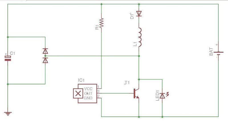
I am going to try a few more configurations like the one in my drawing.
The wave for below is from TP1 on the schematic.


Leave a comment:
-
Thanks, I appreciate. I'm comfortable with bipolar while mosfets are totally new territoryOriginally posted by Farmhand View Post I only burnt one MJL so far and that was my mistake. I used shicklay and totem poles for switching before and they worked well also, in solid state running much faster than this device. I'll give a try. I need to read back all Slider's post. This is interesting.
VLeave a comment:
-
Hi Blackchisel, I don't seem to have problems with my soldering iron and mosfets, I don't solder with it while the circuit is grounded though, only isolated. If I could offer that I think a MJL21194 is a very good switch and probably as good or better in some ways than a mosfet. I do occasionally have Fets that seem to end up ruined and always conducting but it is usually from overvolting them with spikes or something that would also ruin a Bipolar.
I would stick with what you're comfortable with. I'll be using a bipolar I think to try for a similar motor energiser inspired by this thread. It should be a lot easier to drive from a higher voltage for me.
Cheers
Leave a comment:
-
Thanks synchro, it makes sense. I couldn't figure out how such position could warrant triggering of second driver circuit which has to be "on" when the first one is "off". Unless I'm wrong, of course. I never worked with mosfets and it is my understanding that they have to be handled carefully since the static may damage them, as well as transformer type soldering gun should be avoided. Am I correct? Maybe silly question but I started learning on vacuum tubes (my first ham amp. was built on them) and I didn't work with electronics for 20 years, until meeting J.B, couple years ago. I can visualize getting switching part done with bipolar transistors instead but perhaps mosfets are better? DunnoOriginally posted by synchro View Post
VLeave a comment:
-
2nd Hall.
Blackchisel97,
I believe the 2nd Hall definitly shorted the coil, and it's positioning for timing is critical. The discharge has to remain at 180 degrees from the pulse to the power coils.Leave a comment:
-
Synchro, I just stated what happened in my setup. I'm not trying to prove or disprove anything as I try to understand this device. All I want is to replicate what Romero did and have small, self running generator on my table.
I did some tests with shorting coil. Interesting, when I connected neon across and moved sensor I saw neon either glowing in the center or on side. Center glow was at approx. right spot - peak of sine wave (I had scope connected as well). With those spikes plus coils output plus BEMF recovery it seems to be enough. Still, what bothers me is Romero's original design which he wanted everyone to replicate. No caps, no coil shorting, he didn't even mention bifilar.
One more thing; he said that there are two halls, one triggers from small rotor magnets and second from rotor magnets, approx 1mm after magnet passes coil. Is it possible that this hall was used for shorting coils, not for other trigger? Position would be correct. Just thinking loud. There was no other circuit visible beside two driver boards so I'm probably wrong.
VLeave a comment:
-
Hi toranarod,Originally posted by toranarod View Post
Have you attempted to make your drive coils bifilar also, and seeing if you can reduce the voltage, as Slider was able to and still maintain the same RPM's?
Another interesting experiment for you would be from going bifilar to trifilar. Right now, you have 123 going to 4567. Try the following with 1 set of coils and see if there is an increase in wattage... 12 going to 34, 34 to 567. The magnetic field will expand three times within itself, in to out, in to out, in to out.
You are very close and one or both of these items may bring you closer to your goal.
Cheers,
BruceLeave a comment:
-
Bruce,
Her's a quote from Blackchisel97 from above.
"Multistrand in bifilar configuration didn't give better performance, actually, AC was less then single wire".
THAT'S WHAT HAPPENS WITH MULTISTRAND!
You are calling the Tesla Hi Voltage single wire series connected bifilar coil a multi strand coil when it's a two SINGLE WIRE coil in the Null Points analysis, to add to your cronic confusion and spreading of disinformation. He's examining a standard "Joule Thief" type wrap where the current is running backwards against itself in a SINGLE WIRE. Try to understand that Bruce! Multi strand bifilars destroy that effect.
These results were hard won by me after long experimental trials with my Quadfilar Spiral coil, built by me based on your false assumtions, only to get the same negative results as Blackchisel97. Don't further accuse me of not having any builds, or experimental data. Find out why it dosen't work with multistrand instead of trying to pretend it does!Last edited by synchro; 07-04-2011, 05:01 AM.Leave a comment:

Leave a comment: