

-
Leave a comment:
-
Hi Romero!Originally posted by romerouk View Post
Sorry for keeping you waiting!
Yes, i've recived it ( i've just checked the inbox from youtube; i had 22 others pm's)Last edited by mariuscivic; 09-13-2011, 07:44 PM.Leave a comment:
-
LOL Romero, he's very bad at seeing PM's and then he plays with his rotor for hours ;+}
(DeepCut here btw)Leave a comment:
-
Mariuscivic check your PM. I've sent you messages... can you at least confirm you received them or not...
Regards,
RomeroLeave a comment:
-
@ elias, when you look at the litz wire (i hope i wrote it correctly ) it only represents the inner core of say for example the Metatron's cube; so where have the outer circles gone....Originally posted by MonsieurM View Post
hint: you'll find them in the muller set up, just look hard (neo )
)

search this figure, it will give you the right ratios to build the correct coil...It is also called the Nested Circles

compare above picture (fast moving ) if i slow it down and overlap frame by frame (use your imagination) ; you get the outer ring of this:
Last edited by MonsieurM; 09-13-2011, 02:01 PM.Leave a comment:
-
Can someone give me a model # of a 12v regulator to use in place of his variable dc converter? I think it would need to be rated at about 3-5A.Leave a comment:
-
@ Elias Can you tell us the resistance of one of your 1mm strands? The pic is yesterday's progress.Attached FilesLeave a comment:
-
-
Thank you! (sorry, i didn't see the pm's)Originally posted by qvision View PostLeave a comment:
-
Leave a comment:
-
from: Flower of Life - Wikipedia, the free encyclopedia
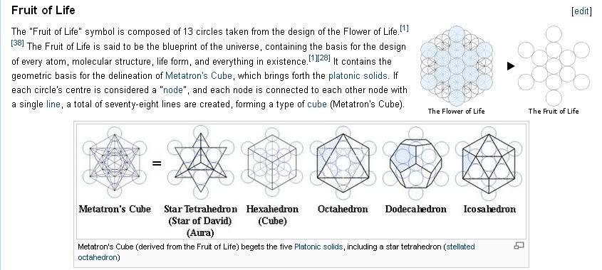
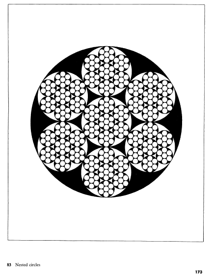
ps: if you follow the lines connecting the inner nodes, you know which to connect to (or short) and it should reflect the how you set up your other rotor magnet (from within so without; it's all in the geometry )
see also:http://www.energeticforum.com/156769-post740.htmlLast edited by MonsieurM; 09-13-2011, 01:46 PM.Leave a comment:
-
The first test I did was making a 5 filar coil, and what I did was that i shorted them one by one, and as i shorted the first one, the RPM dropped say about 500 RPM and then as I shorted them one by one, at each one the RPM rose 50 RPM.Originally posted by toranarod View Post
That coil had smaller gauge wire on them and much less turns
Then I did that test with a coil I had built years ago. What kind of diagram would you like me to show you. I will reproduce the effect this afternoon, and hope to be able to make a video to demo it.Leave a comment:


Leave a comment: