This forum is preserved as a permanent archive. The community continues at eMedia Press.

Announcement

Collapse
No announcement yet.

Multifilar Generator Coil - Lenz delay Experiments

Collapse
X
 
  • Filter
  • Time
  • Show
Clear All
new posts

  • SkyWatcher
    replied
    Hi bromikey, thanks for the reply and positve words.
    Well it wouldn't be perfect, since just as 2 of the magnets, (180 degrees from each other, as seen in the photo), are needing to be pulled away from their cores.

    The other 2 magnets which are 90 degrees or so from the other magnets, need a little more rotation to start pulling hard at their cores.

    So it would be at least a 50% or more improvement, at neutralizing the magnet cogging issue, I think.
    Actually, 6 core/coils might be an even better geometry, for reducing magnet cogging, I'll look at my cad program in a bit and check that.

    Was working on the motor arbor again today.

    Picked up a few, actual small allen set screws.

    I tapped threads at both sides of shaft on the nut coupler.

    Also had to shim the shaft with one layer of aluminum tape, (though not sure how the tape will hold up) that solved the centering and wobble issues, as did the set screws.

    Then used some blue loctite on the set screw threads, as they came loose on first test run, with just the core in place.

    Will test run it tomorrow for a bit and see if it can hold together or not, will use super glue on threads if need be.
    peace love light
    Last edited by SkyWatcher; 06-20-2019, 03:46 AM.

    Leave a comment:


  • BroMikey
    replied
    Originally posted by SkyWatcher View Post
    with 4 core/coils, with the 10 magnet rotor, it might not be too bad.

    As It rotated in the cad program and it showed that when a magnet set is ready to move away from the cores, another set of magnets would be pulling strong to help move those away from their respective cores.
    Yes that is worth a try, good thinking can't wait. If I had 4 cores I might
    do that test as well, someday. 4 core correctly spaced would lower the
    price way down.

    Leave a comment:


  • SkyWatcher
    replied
    Hi all, Hi bromikey, thanks for sharing the good information.
    Yes, don't think my setup at the moment will be too much an issue, as it starts up fine, though with more core/coils, probably not with this motor.

    Though with 4 core/coils, with the 10 magnet rotor, it might not be too bad.

    As It rotated in the cad program and it showed that when a magnet set is ready to move away from the cores, another set of magnets would be pulling strong to help move those away from their respective cores.

    Hi lotec, thanks for the positive words.

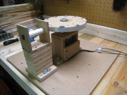
    Been busy working on the workshop in shed, it was taking on water, think we fixed that problem and we made the work bench 24" deep for these type of projects.

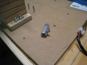
    Also had to screw the project board down to the workbench, as the core/coil holding structure was causing a little flex of that board, when the magnets passed, now it is better.

    Then I also realized the one set screw in the arbor was not sufficient to keep the shaft centered and secure inside the arbor.

    So I'm working on drilling and tapping 3 new set screws at equal points around the arbor.

    That should do the trick, they are for 3/16" diameter bolts or set screws, which should give more stability and be more secure, especially with blue loctite added if needed.

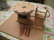
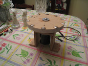
    Here's the new workbench and progress of arbor..
    peace love light


    Leave a comment:


  • lotec
    replied
    Nice work. Nice stater. Radial machines are good that they can present an endless stream of flux cutting copper, but harder to engineer , for low drag, than axial machines. Faraday's macine could present an endless steam of flux cutting copper , but had other issues. Please share how Hallback array works, for low drag.

    cheers.
    Last edited by lotec; 06-18-2019, 10:47 AM. Reason: to clarify

    Leave a comment:


  • viomarmi22
    replied
    I will build a generator with magnets placed in halbach array mode. I have already bought 40 pieces of magnets and I will still buy 40 pieces, the rotor will be external to the electric bicycle hub, so I can experiment with different types of stators. If there are any grammatical mistakes, I use google translate, I am Romanian and speak Italian only, so please excuse me!https://www.aliexpress.com/item/2-pc...27424c4ds056EX
    Attached Files

    Leave a comment:


  • BroMikey
    replied
    You can do both tests and should. "N" "N" "N" is one test.
    Here is what i am looking for.

    200ma @100v for 1 of the 3 channels on a single AUL coil. X 3= 50-60 watts and this is
    with weak magnets and #23 wire. Magnetic cancellation as well.

    24vdc input was and will be 2 amps at running speed. Go figure. Originally I run a
    modified motor at 20vdc at 2 amps and got speed up with the huge 50lb magnets on
    my 20 magnet 10" rotor, taking 5 amps for start up smoked my modified, redid the
    winding and am now ready to try again.

    Gonna run a standard scooter motor first which leaves me some head
    room as before I needed a clutch to reach run RPM's, remember?

    Yeah extra power to get her up to speed. Learned my lessen, gotta have
    cancellation.

    Now with the small rotor and weaker magnets it won't be a problem
    to get up to cruising speed even without cancellation. Again both
    tests are in order.
    Last edited by BroMikey; 06-17-2019, 08:40 AM.

    Leave a comment:


  • SkyWatcher
    replied
    Hi all, the project is moving along, waiting for the paint to dry on the rest of the core pieces.
    Though I will probably test the north-south magnet rotor as is, then probably make it an all north out magnet rotor after that, to use turions counter permanent magnet neutralizer method.
    peace love light

    Leave a comment:


  • SkyWatcher
    replied
    Hi bromikey, yes, that is a good idea, It will have protection around it for sure.
    Though it should not need 3000 rpm to achieve lenz neutral and if 2300 rpm is not fast enough, well, I'll make a new coil then.

    I finished the rotor and it is balanced pretty well, used lead from an old, large bullet that was found in a field.
    Though had a little issue with wobble, a steel washer configuration solved that.

    Hi pot head, yes I have space restrictions at the moment and I don't plan on ballistic speed with this rotor, though would like a slower rotating design, as long as it can get lenz neutral effect.

    peace love light

    Leave a comment:


  • Pot head
    replied
    SkyWatcher

    Do you have space restrictions for your build?
    John Bedini wrote the bigger the better= slower rotation.
    If balanced it can run super fast and safely.
    I had my now broke wheel generator running so fast It sang but it scared the Shiite out of me.
    I ran it slow on 24 volts to charge the battery bank for my inverters to run my house.

    Leave a comment:


  • BroMikey
    replied
    Nice big magnets, not my favorite design but that is okay for testing
    if you don't get injured during 3000 rpm operation. Yes use some
    bricks like short chimney all around the project, lead is to costly

    I think the key issue (just guessing) with clear tape is that this design
    makes it more trouble to get a tight gap and in the process some of
    the tape and magnets will come into contact. You know what they say
    about one weak link in a chain.

    Since you are using such powerful magnets your plan was probably to
    use a wide gap. Good idea. Lexan also works well for flying magnets.

    Sand bags?

    Great job balancing. I see many ways to balance, tiny
    bearings when standing up the rotor vertically. Then there is the
    horizontal balancing act like a magician holding up a plate in the
    center with 1 finger.

    Have a good day.


    Leave a comment:


  • SkyWatcher
    replied
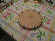
    Hi all, the new 8" diameter magnet rotor is coming along.

    Almost done super gluing them, then will add fiber tape reinforcement around the periphery.

    Will probably have to rebalance after that.
    peace love light

    Leave a comment:


  • SkyWatcher
    replied
    Hi all, Hi bromikey, thanks for the helpful information and positive words as usual.
    That's not cheating, that is being creative and trying not to reinvent the wheel.

    Hi turion, thanks for sharing the nice rotor pic and information, I see it has the narrow magnets for the slower rpm effect, nice.

    I was working on the simpler rotor today, I made it 8" diameter this time.
    Yes, used mdf again and was able to balance it out well with a little lead weight.
    Again, I used the hand jig saw to cut the rotor, which is not ideal.
    I usually use a circle jig with a plunge router and that has always worked pretty well, just got lazy I guess.
    Also, the rotor will have 10 magnets this time.
    Next step is to bore the magnet holes in the radial edge a 1/2" deep.
    Will then probably have to rebalance the rotor with the magnets in place.
    peace love light

    Leave a comment:


  • Pot head
    replied
    Nice work, thanks for your
    dedication and valuable time.

    Leave a comment:


  • BroMikey
    replied
    Originally posted by SkyWatcher View Post
    I put all the magnets in place and spun it up on the 12 volts and it
    was not too good.

    Remember that I cheated? I use HIGH SPEED SAW BLADES. Here is what
    I know about randomly designed materials. machines randomly blow
    out fibers and chip with varying amounts of glue, press it out heated.
    They were never meant for high speeds. Such materials must be
    balanced later. Wood is no better, this is why some portions of randomly
    produced materials will be indestructible on one side and crack on the
    other seemingly without cause.

    On the other hand light weight board has it's place for mounting and
    fixtures. Now take a piece of plastic, it is uniform throughout it's
    entire mass. Lexan is so awesome, scientifically formulated to stop
    bullets but every sq inch is exactly the same as the next just like
    poured steel, aluminum and brass.

    Another thought is that you can chuck up a 12" circle of Styrofoam
    spinning it effortlessly without vibration until you start hanging
    weights on it's outer perimeter you find just how precise it needs
    to be.

    I know all this so me cheated My first one was a 10" tablesaw
    blade using the arbor from off of a table saw ordered from ebay
    used at $20 measly bucks Think of it. I let everyone else
    do the work for me. That is why I am looking at auto flywheels for
    a possible future rotor. They are already balanced good to 10,000 rpm.

    So you see, i feel your pain. But how else ya gonna learn?

    You are an advanced builder way ahead of the curve, nothing stops you.
    Stick with me, I won't let you go unchecked.

    Last edited by BroMikey; 06-11-2019, 09:43 AM.

    Leave a comment:


  • SkyWatcher
    replied
    Hi bromikey, thanks for the positive words.
    I put all the magnets in place and spun it up on the 12 volts and it was not too good.
    So I shimmed, then had it fairly true and when i took the rotor off and put it back on, the rotor was out of true again.
    It's useable, though at higher rpm's, It might put too much stress on the motor bearings.

    So, I plan to make a new, simpler, radial rotor, without all the time consuming spacers.
    The 1/2" deep magnet holes will be drilled into the periphery of the rotor, superglued in place and fiber tape reinforcement.
    It might be a smaller diameter rotor this time, will have to draw it on cad and see how it works out.

    Hi netica, thanks for the good information, will probably use those tips.
    peace love light

    Leave a comment:

Working...
X