This forum is preserved as a permanent archive. The community continues at eMedia Press.

Announcement

Collapse
No announcement yet.

Multifilar Generator Coil - Lenz delay Experiments

Collapse
X
 
  • Filter
  • Time
  • Show
Clear All
new posts

  • SkyWatcher
    replied
    Hi all, been working on the project today.
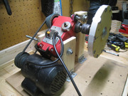
    Had to remount the drill press lower to meet the coils.
    She is running pretty sweet, even without a balancing core/coil on other side of rotor.
    Next step, is to wind the prepared 26 strand coil onto the bobbin.
    peace love light

    https://youtu.be/qUQR_VZL66o

    Leave a comment:


  • SkyWatcher
    replied
    Hi bromikey, thanks for the reply and positive, encouraging words as always.

    Think it will be ok, a clamp was required to fully seat the magnets, could always add a couple dabs of superglue.

    Yes, they are now all same polarity on one side.

    Tested it on the drill press motor and it has virtually no wobble and is running true (balanced) without any balancing weights.

    Should allow for some close tolerances.

    Should explain the method used to build this rotor, as it resulted in a good magnet rotor.
    Used a metal compass and lightly gouged the circle template.
    Drew 8 lines from center punch mark to edge of discs.
    Then used a jig saw (ideally a plunge router, my universal plastic guide is broken) to cut out three 8" diameter discs.
    Then drilled center shaft hole through all discs, with drill guide (ideally drill press).
    Then lathed all three, 1/4" mdf discs, bolted together at shaft hole.
    Now, since the periphery of the discs are all perfectly round, relative the center shaft hole, it was easy to measure down each line 1" and use a metal punch to mark each drill hole accurately.
    Also, draw a reference line across outer edges of all discs clamped together, using permanent marker, so they can be realigned when needed.
    Then with only 2 of the mdf discs clamped together, used a 1" diameter fostner drill bit for each magnet hole, which gives a tight fit.
    Then clamped all 3 discs together again, lining up the reference lines and bolting center shaft lightly snug.
    Then used many clamps around the outside of the rotor and super glued the seems, all around the periphery of the mdf discs and let dry over night.
    Then lightly lathe any excess glue if needed.
    Then insert magnets.
    Done.

    peace love light

    Last edited by SkyWatcher; 06-28-2019, 02:42 AM.

    Leave a comment:


  • BroMikey
    replied
    Sounds like you are honing your skills. The lathe is so good for
    wheels or rotors. One thing, I have one of Dave's rotors here and
    we all know how he talks about putting magnets back to back with
    a spacer in the middle of the rotor layers. This spacer is very thin
    at 1/6" solid plastic. You see at 1/4" the magnets pulling power is
    almost gone, so be careful.

    Great progress keep trying. Glad to here you are going for the
    "ALL NORTH" polarity on one side and "ALL SOUTH" on the other side.

    Also that you are seeing the importance of building the rotor so
    tolerances can be kept to a minimum. You are on your
    way to O.U. production.

    Leave a comment:


  • SkyWatcher
    replied
    Hi all, another project update.
    Ditched the aspen material rotor, apparently it takes better machinery to lathe that type of wood.
    So, went with the original idea.
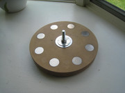
    Used 1/4" mdf, 3 discs at 8" diameter, with 8 neo magnet holes.

    The middle 1/4" disc is solid, being used as the permanent magnet spacer, to cause the magnets to attract each other.

    Will also place the magnets all same polarity on one side.

    The magnet rotor is being super glued at the moment, with a ton of clamps.

    Was able to lathe it perfectly round and it has virtually no wobble.
    peace love light
    Last edited by SkyWatcher; 06-27-2019, 01:55 AM.

    Leave a comment:


  • SkyWatcher
    replied
    Hi all, been working on the project some more today and decided to build another magnet rotor.
    The magnets are inset into the wood, like the first rotor that was built.

    This rotor is made of aspen wood, 8" diameter and 8 neo magnets this time.

    Made this rotor for safety and to be able to place a core/coil on each side of the rotor for better structural balance.

    Also, will make the magnets all north out on one side, to be able to test turions magnet lock neutralizing method at some point.
    Will probably use the same spacer method between rotor magnets, so they attract each other, to lock them in the rotor better.
    peace love light

    Leave a comment:


  • SkyWatcher
    replied
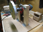
    Hi all, the drill press monster modification is coming along.

    It took quite some time brainstorming this thing, had to just look at it, ponder it and come up with ideas.

    It's fairly rock solid now and more core/coils can be added later with a sheet of wood in front of the magnet rotor, with I-beam type reinforcement at back of board.

    Will just have one core/coil to start testing at bottom of magnet wheel.
    peace love light


    Leave a comment:


  • SkyWatcher
    replied
    Hi all, Hi bromikey, thanks for the positive words.
    Yes, have realized that separate shaft and bearings works better, as have built those in the past, just wanted to see if I could get a homemade arbor to work with out lathes and such.
    Could still use back to back drill chucks for the scooter motor, though think this drill press setup will work fine for now.
    Hi quantum well, yes, will try and be safe, thanks for the concern.

    Hi turion, thanks for sharing the drawing.
    Was thinking about having the rotor in a vertical position, pretty much similar to what you are showing in the drawing.
    Might be safer also and the flat board that the coils sit on might have less flex, being vertical and using I-beam type supports behind the board.
    peace love light

    Leave a comment:


  • Quantum_well
    replied
    Safety.

    I think something like a full face motorcycle helmet with
    polycarbonate visor would be in order.

    Leave a comment:


  • BroMikey
    replied
    Nice setup. You can get those drill presses for not to much and
    is a perfect pick for a fast test rig with variable speeds. Nice.

    Now you can see the significance of having a rotor have it's own
    shaft and bearings.

    Leave a comment:


  • SkyWatcher
    replied
    Hi all, thanks for the positive replies.

    Decided to change the setup, since my homemade motor arbor is not working as well as hoped.
    So, had this drill press collecting dust and some rust and decided to use it rotate the magnet rotor.
    The rotor now stays true and rotates the magnet rotor almost perfectly.
    Still need to think about how to mount it and the coil/core bobbins.
    peace love light

    https://youtu.be/uDQhnrIVfj4

    Leave a comment:


  • Pot head
    replied

    Leave a comment:


  • bistander
    replied
    Simple request

    Originally posted by SkyWatcher View Post
    ...
    Here is a video of it running at 12 volts, with just the core in place. ...

    https://youtu.be/8kjUei--LUU
    Nice video SkyWatcher. Can you please measure volts and amperes with and without the core in place. RPM for both cases would be nice if you have a tach.

    Thanks in advance,

    bi

    ps. Another interesting test would be to run for a while with the core and record the temperature.

    Leave a comment:


  • SkyWatcher
    replied
    Hi all, an update on project.
    I decided to try and get the small wobble out of the magnet rotor rotation, somehow.
    So on examining further where the problem is, yet again, it is the arbor-shaft interface.

    So my final effort to solve the motor arbor issue is this.
    I have used full strength jb-weld, and globbed it onto the motor shaft.
    Then used masking tape to protect motor bearings and then wrapped a masking tape former around the globbed on epoxy, so it will cure more uniformly.

    When the epoxy fully cures by tomorrow, the motor will be powered on and a metal file will be used to machine the epoxied shaft to the correct diameter, to fit the nut coupler/motor arbor.

    Wish me luck.
    peace love light

    Leave a comment:


  • SkyWatcher
    replied
    Hi bromikey, thanks for the encouraging words.
    Yes, It's been tricky getting this homemade arbor to work well, I think I am onto it though now.
    The slight wobble seen in the video, I'm sure that can be resolved as well.
    The blue loctite seems to be working well though and with at least another core on the other side, that would balance things better and reduce vibrations.

    Next step is to wind the already prepared, 26 strand coil, onto the core/coil bobbin.
    Here is a video of it running at 12 volts, with just the core in place.
    peace love light

    https://youtu.be/8kjUei--LUU

    Leave a comment:


  • BroMikey
    replied
    Originally posted by SkyWatcher View Post
    Hi bromikey, thanks for the reply and positve words.
    Well it wouldn't be perfect, since just as 2 of the magnets, (180 degrees from each other, as seen in the photo), are needing to be pulled away from their cores.

    Will test run it tomorrow for a bit and see if it can hold together or not, will use super glue on threads if need be.
    peace love light

    I feel your pain

    From what I read if you have 8 hard magnets the best it to use either 7
    cores or 9 cores and if it is maximized the best that can be achieved
    is the equivalent of 1 magnet to 1 core cogging resistance. Less that
    perfect means same as 2 core cogging to break the lock.

    Still this is much better than all of them locking up on you all at once.

    I get a big kick out of your progress, stay at it, you will be in pole
    position sooner than you think. There are a bunch of guys who will
    follow you.

    NOTE: If you get time check out the SERIAL BRAIN 2 decodes we are
    living in historic times.

    Leave a comment:

Working...
X