
Hi SkyWatcher,
I make alot of things out of mdf like your rotor in the video.
Be very careful when you put magnets in it as there will be alot of stress on the mdf board and its only wood. I would put a couple of bricks between the rotor and yourself in case the rotor should fall apart. I have a rotor like yours that I have used for other experiments but I have only ever had it up to 1000 rpm. It is 200mm in diameter.
Mdf is very useful and easy to work with. I also print out a design like yourself to cut out mdf.
I will explain a good method I use to get it onto the mdf.
Get your piece of mdf that you want to cut out and another of roughly the same size to use as a pressure plate.
I use spray glue from a craft shop.
This is very important. Spray the mdf only, with the glue (not the drawing) applying an even coat. Allow to dry for a minute or two. then place on the drawing and just let it down evenly onto the glue/mdf.
Now get the other piece of mdf and place it on top of the paper and apply pressure evenly onto it to press the drawing onto the glue.
and that's it.
By doing it this way the paper doesn't stretched or get distorted in any way. It took a while to get this right, but it is the best method I have come up with so far.
Here is a link to something I made using this method some time ago - https://www.youtube.com/watch?v=9kqN7ihsOyM
Hope this may come in useful.
-
Originally posted by SkyWatcher View Post
Pretty decent is right and when you get the magnets on it will be just
as smooth if not better, course you can get any better. The thing ain't
even tied down and there is no vibration. Pretty sweet deal, oh and
thx for the pat on the back over my new bobbin.Leave a comment:
-
Hi all, here's a video of the rotor running on 12 volts.
It should work ok, have to try it with magnets installed yet.
peace love light
https://youtu.be/KbOO4pOXEp8Last edited by SkyWatcher; 06-10-2019, 07:30 PM.Leave a comment:
-
Hi bromikey, glad to hear you're making good progress with your setup.
Just applied power to my motor and unfortunately, the cad paper template method did not work out perfectly.
Normally, I use a router with circle jig, then mark the magnet holes with protractor and ruler and that has always worked fairly well.
I noticed you said you have used a shim method for getting the center hole more centered.
I'm going to try that with some steel wire garden wire.
If it does not work, I will build another rotor with the router method.
peace love light
Edit: ok, used a small piece of steel garden wire next to 3/8" bolt and it worked to center rotor much better, almost perfect. Also needed 2 large steel washers where rotor meets nut coupler arbor, as 1 washer caused up and down wobble.
So I take back previous comment, the cad paper template does work pretty good, more likely my hand drilling methods, that are to blame.
Have no idea how it will be when the magnets are in place, so we will cross that bridge when we get there, I will not glue them in place until it is tested in rotation, the magnetic fields should hold them in place for this testing.Last edited by SkyWatcher; 06-10-2019, 03:33 PM.Leave a comment:
-
Yes, I did some more core work and now doing the bobbin so
it is going to be a while since I must also finish the fitting on
the second generator school project. It has 10 magnets that are
10mm dia and 15mm long.
The frame needs some work, just adding bracing and then formulating
the best mounting that can still be adjustable to center the "C" core.
Also my magnets must be set in the specialized epoxy in the magnetic
shield/holder/adjuster. The thing that kept progress going slowly was
not having a decent core that I could think up, then I stopped to build
the other slow moving school experimenter. The cores and bobbin is
critical.
I have motors (DC scooter) and the rotor mounts, drive coupler. The
framing was a big job and it is looking great. All measurement are
good on spacing so the "C" cores can be set in with shims and locked
down. It's quite a piece of art work. It may not look like it to others.Last edited by BroMikey; 06-07-2019, 01:26 AM.Leave a comment:
-
Hi all, Hi bromikey, thanks for the positive words.
Yes, I hope it's a good, practical level of output.
Ok, that's good to know, that I might get 2 channels of at least neutral lenz for power output.
I look forward to seeing how you and your sons multifilar gen. project comes along.
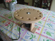
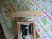
I finished the motor assembly.
peace love light
Leave a comment:
-
Thx Sky and nice work to you too. You will get an easy 2 channels of
over 1000 ft each. I like going over some during testing to get a major
relief on the drive motor, so much fun and at the same time produce.
Lets see where was I one day, yeah I had 170foot strands using 8 of
them at 1300 plus feet and it was starting to speed up just a tiny while
maximizing coil output. You will have 2 circuits producing.
You seem to be one of the few who gets it. #24 it a whole new
level of output.
Someone has to take the lead
Leave a comment:
-
Hi all, Hi bromikey, nice work and nice coil you have going there.
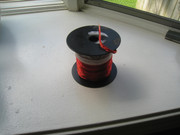
I finished my first coil, I integrated the other 12 strand coil I had, though that means I had to make the strand length shorter.
Specs:
26 strand multifilar coil
110 feet per strand
24awg. magnet wire
46 ounces of copper
Might be good, will continue working on project.
peace love light
Leave a comment:
-
WOW!!! nice hardware fella, looks like my multifilar Bedini coils.
You've working overtime.
Leave a comment:
-
Yeah? Oh, yeah? Well!! Oh! Yeah? ☕️
Similar to this kind of thing but tailored to your build.Attached FilesLeave a comment:
-
-
Question
If you would have left the extra length of wire,
how would it result in your circuit?
Would there be any difference?
If not, why not coil the extra length in smaller
tight coils to act as a spring slack remover?
Attached FilesLeave a comment:
-
-
50 strands 75ft long after cut offs now 74ft less the lead in and lead
out wires so say 70ft per coil. 2" wide an about 1.5" thick on each side of
the core. So plenty of room to fit on my "C" core as shown.


Leave a comment:
-
@SKY and all
Me (old man Mikey) and my pretty boy son Jordan
[VIDEO]https://www.youtube.com/watch?v=fzZ0Es-Iz8U[/VIDEO]Leave a comment:
Leave a comment: