
Originally posted by Turion
-
So thats how many turns on the core before you series the 8 together? And, your output voltage ( open circuit )... and your short circuit current if you have that as well... Ok, one more edit.... the resistance of the coil as it's used for the output ( 8 in series I'm assuming ).Last edited by dragon; 07-16-2019, 02:10 AM. -
Much thicker stator core also.... the 10si core on the right was also hand wound with small wire where it would normally be wound with 18 ga or larger. Most of my 100 amp units had 6 turns per coil of heavy wire but they needed 2000+ rpm to make 14 volts. Their trying to get a much higher voltage at lower rpm so their most likely using 18 to 20ga or smaller. I've hand wound hundreds of those 10si cores. Got a big basket of parts left over from those days and still have a couple complete units on the shelf.
I've designed a simplex motor using some parts out of one that I'm machining parts for in my spare time currently.
What would be interesting for you guys to test would be a simple air core coil following some simple rules. I don't know the magnets your using but I'm assuming their the standard round units. So, the coil center must be the same diameter as the magnet, the width of the coil legs should not exceed the width of the magnet - for instance the total diameter shouldn't be more than 3 x the diameter of the magnet and the magnet should drop through the center. You want to keep the thickness of the coil about the same thickness of the magnet or slightly larger - the thicker you go the less flux saturation on the rear of the coil.
Figure out how many turns you have with your current set up and try to match that with the largest wire that you have real estate for following the parameters above. This is just a simple air core coil which wouldn't take very long to make. Run the same tests your currently doing with both the coils.
Chances are you won't need as many turns per coil to achieve the same output voltage so matching the turns may be a bit higher. Since there is no iron you can close the gap for clearance only - there will be no cogging and start up will be instantaneous. Since your using only one pole - only one coil leg at a time will produce an output as the magnet passes over. This will still show an AC wave output as it passes each side of the coil. Using NSNS layout the output will be double plus as long as the NS are positioned over the coil legs.
Just a simple low cost comparison....
Edit: if this isn't clear let me know and I'll draw a diagram of the layout and coil sizes.Last edited by dragon; 07-16-2019, 01:56 AM.Leave a comment:
-
You are where I am. Where is that? learning to match flux or strongOriginally posted by SkyWatcher View Post
magnets with the core size and type.
Test for core material.
Take a paper clip and set it on the core end right after running it for
a few minutes. If the paper clip stays on the core you have a magnet
instead of a core.
Suggestion. Take an old microwave oven (MOT) apart by grinding off
the factory welds. Taking the "E" section off of the base. The base welds
can be ground and you will get some grain oriented steel that will
measure 4" long X 7/8" then using an old knife find the number of
leafs you want for say a thickness of 7/8" and strike the back of the
knife with a hammer gently. Tap each side til your block pops off.
Or I think Turion uses buck shot forced tightly into a tube with epoxy.
I have not experimented with wire cores so I don't know. All I use is the
state of the art transformer steel. I am about to try 25awg wire but
know nothing yet. I am where you are, trying to find combinations of
core material to strong magnets to see what i can generate in the way
of power output.
Excellent to hear the magnet that is set in opposition the attraction
side at the core is working enough to get it running.
You need to find the null and you should already be seeing huge
speed up at 26 serial strands. You will need to lower the drive voltage
on your ac induction motor to see small changes.
For instance, with my 5 amp induction motor, it was so powerful at
120vac that the amps were about the same but I noticed little effects.
Or you could put a big pulley on a DC scooter motor and belt up.Leave a comment:
-
Hi all, ran some more tests today.
Moved the rotor magnet to core gap, to 1/16" and also flipped the core/coil around, so that the magnets are closer to the coil as they sweep through, because the other side has the 1" core protrusion.
It does seem to help with power production.
2 power channels, or 26 strands in series = 17.5 vac over 25 watt incandescent bulb and input watts stay the same.
1 power channel, or 13 strands in series = 47 vac over same 25 watt bulb and input watts increase.
So only getting about 1/2 watt through bulb, with 26 strands in series and input seems to stay the same.
And getting around 3.7 watts with 13 strands in series, though input increases then.
Motor cannot start without the magnet neutralization in place, it just sits there without it, so that's a more positive thing so far.
That's all for the moment.
Not sure this coil is doing it, or the rotor speed or magnet count is too low.
peace love light
Leave a comment:
-
Being a small unit they most likely have to use smaller wire with lots of turns to achieve a reasonable voltage level for transmission as well as making the best of the real estate available for the wire and keep the rpm's within a reasonable range for the blade design. With something that small their probably using blades that run in a TSR range of 7 to 9 which is pretty fast.
I started building 3 phase air core alternators in the late 90's. Much more efficient and very light weight. I used to have custom triangle magnets made, not for the cogging - specifically for the magnetic surface area over the round or rectangular to advantage the real estate for maximum copper. Still have a few hundred of these in a box I use for my own toys... The stators were designed for the lowest possible resistance as well as ultra low rpm operation.
Given this background I can see a few flaws in the solenoid style alternator design, I understand your reasoning for the design but with a few design tweaks you may end up in a much more efficient place.
The low Lenz design that I posted doesn't stop or lower the lenz force ( we need this for a powerful output ). What it does is divert the force away from the rotor - that is - because the magnets are stationary and the stator coils are stationary the Lenz force is diverted into the solid mount of the case. The rotor simply directs the polarity. There is still a slight force working on the rotor but most of the Lenz force is against the magnet and stator. I posted a video of the stator wound with 8 ga wire producing 28 amps in that small fan motor conversion. Even at very low rpm the current output is very high for it's size. https://www.youtube.com/watch?v=dordyphTKFs
In any case, I know you guys will figure it out... I'm simply a curious observer in your project.Leave a comment:
-
They all used triangular poles to remove the cogging problem.
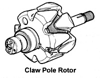
Skewing the stator slots was most likely a far less expensive alternative to having custom triangular magnets made.
Back in the 70's we modified the delco 10si by pressing out the shaft, removing the field coil and replacing it with ceramic magnets ( cheap speaker magnets ). It was about the only way to set up a DIY wind gen without having to run power up the pole to drive the field coil.
The purpose of lots of turns of smaller wire is to bring the voltage up so the transmission lines can be small diameter lines run into an MPPT controller then converted to what ever is required by the battery bank or grid tie.
In any case it's pretty much all basic design since the 1800'sLeave a comment:
-
Duh "Our Markets wouldn't let us go outside the box, duh. Get a lifeOriginally posted by bistander View Post
inside the subject matter which takes more brain matter, zero lenz
and zero drag plus zero cogging. What is this?
Mitigation is spelled wrong but it is a big word that you should be
so proud to have in your vocabulary. We can't have Lenz mitigation
my goodness no.
Turion is right again that these guys have figured out a way to stop
the huge cogging at speed as well as on start up. Good idea to use
twice as much copper and wound the right way, HUH? Right?
Poor Bi he tries so hard to chin up to the pro's, makes a good sound.
Last edited by BroMikey; 07-15-2019, 08:46 AM.Leave a comment:
-
PM alternators
Hi Turion,Originally posted by Turion
I guess you now accept that generator principles and physics used in machines with square or rectangular coils and magnets apply to yours using round poles. Remember this?
Here was your reply.
I doubt you took the time to download and read it. However I am interested what your research brought up. Can you provide and link or search phrase? Google was uncooperative. Missouri Jeff had a nice looking stator core. More representative of the machines on which I worked. I don't recall ever doing a round poles machine. Most used around 40 to 50 coils. None had skews. Our markets didn't require cogging mitigation. I think our automotive division did skew the heater blower and wiper motors. Some use it, some don't. All I am saying is that "your magnetic neutralization" is worthless at 2800RPM, 2kw. It is merely a distraction.Originally posted by Turion
Regards,
biLeave a comment:
-
Some might.
Bound to be criticism but some might find this interesting.
Leave a comment:
-
You are smart to follow me. I am not sure about all dimmers but someOriginally posted by SkyWatcher View Post
of them will be able to handle start up and others will pop. Find a 6amp
fan dimmer and I think they go down to 90 volts of pulsed AC from a
triac.
I also looked on ebay for month till I found a good variac for cheap.
I ac motor engineers talk about SLIP and refer to the air gap, bottom
line is a line voltage these motors are fixed for one speed at full load.
The speed don't change but the volt drop will lower the motors ability to
go full load
https://www.ebay.com/itm/Variac-Transformer-Variable-AC-Voltage-Regulator-1000w-Metered-AC-110V-10Amp/202466501095?hash=item2f23f1a1e7:g:ypQAAOSw~QhbvyN KLast edited by BroMikey; 07-14-2019, 10:28 PM.Leave a comment:
-
Hi all, Hi bi, thanks for sharing the information.
Hi bromikey, thanks for the positive and good information.
Yes, the core you have is nice for balancing the rotor.
Don't have any large enough dc motor on hand here, or at any local shop except maybe a different surplus shop that am aware of, to swap out the drill press motor.
Though maybe will pick up a dimmer just to test it, since the test durations are not very long and this motor can be replaced.
So next step, will be closing the gap to at least 1/16", then use dimmer to lower input voltage, to make rotor speed changes more obvious and adjust coil strands in series.
peace love light
Last edited by SkyWatcher; 07-14-2019, 04:15 PM.Leave a comment:
-
Originally posted by SkyWatcher View Post
@ BiOriginally posted by bistander View Post
It isn't bad mouthing, it's called correcting you for your inability to follow
the data presented for this build. The goal is to see any amount of power
that can be generated without dragging down the speed of the rotor.
Since you are not building this design it is a foreign subject matter
when comparing flawed data. We are not after resonance or levitation
we are building coils that are free from lenz law.
@Sky
If you get enough flux from a magnet the length of the core won't
stop you from reaching the null or speed up. Close the gap and add
all of the winding in series. 26 strands will speed up the rotor . From
there you can back off a few strands at a time til you get the null
point. If 26 strands does not do anything much it is because you need
to close the gap. Most small motors are gapped at half a 1/16th or less.
My new coil is 25awg. As you already know the purpose of having single
magnet thru the rotor coming out on each side with a "C" core is to
close the gap without undue stress or to self center the stress on the
magnets or balance out the pull. I would be afraid of your stacked
magnets that I think you said are glued together when closing the gap.
You have a barrier, great.
It is also possible that your drill press motor is just to powerful to
notice small fluctuations. this is why I weaken the power of my AC
dishwasher motor by using a Variac. What I found was that running
my Ac motor at 120vac or 85vac the rpm's were the same with no load
on it. The lower voltage is better for measuring load changes, much more
sensitive. My motor is like yours, it can run at 5 amps. All I needed was
1-2amps.
Do you have a Variac? Or a dimmer switch for a ceiling fan? Or
throw on a dc motor.
Last edited by BroMikey; 07-14-2019, 07:14 AM.Leave a comment:
-
Maximum power transfer
Hi Sky,
Please look into the matter. By increasing RPM you should see an increase in output voltage. Which you did. But instead of following my advice, you wired the 2 channels in series. Yes, that increased OC voltage, but with your load choice, sent you further away from matching impedance. Matched impedance is a big deal in area of AC power. Ever notice how HiFi speakers and amplifiers are matched?
So when you put the 2 channels in series, the coil's resistance went to 62 ohms. From the lamp's rating, load resistance in about 600 ohms. You must not of saw much power as you did not measure it.
The previous test used one coil channel (31 ohm) and a 10 ohm load resistor. You recorded 0.89 VAC, or .79mVA.
If you run 2 channels in parallel (15.5 ohms) it will be pretty close to matching a 10 ohm load. Or if you have 3 of those resistors, configure for 15 ohms. That will show you the maximum power with that configuration. Then cut the air gap in half and really increase power.
BM and Turion like to bad-mouth me. But I've got many years of education and experience with this technology. I know what I'm talking about. Don't believe me? Check me on the maximum power transfer therom. Or run the test I suggest.
Whatever. Thanks for sharing the data.
Regards,
biLeave a comment:


Leave a comment: