This forum is preserved as a permanent archive. The community continues at eMedia Press.

Announcement

Collapse
No announcement yet.

Multifilar Generator Coil - Lenz delay Experiments

Collapse
X
 
  • Filter
  • Time
  • Show
Clear All
new posts

  • alexelectric
    replied
    Originally posted by dragon View Post
    Being a small unit they most likely have to use smaller wire with lots of turns to achieve a reasonable voltage level for transmission as well as making the best of the real estate available for the wire and keep the rpm's within a reasonable range for the blade design. With something that small their probably using blades that run in a TSR range of 7 to 9 which is pretty fast.

    I started building 3 phase air core alternators in the late 90's. Much more efficient and very light weight. I used to have custom triangle magnets made, not for the cogging - specifically for the magnetic surface area over the round or rectangular to advantage the real estate for maximum copper. Still have a few hundred of these in a box I use for my own toys... The stators were designed for the lowest possible resistance as well as ultra low rpm operation.

    Given this background I can see a few flaws in the solenoid style alternator design, I understand your reasoning for the design but with a few design tweaks you may end up in a much more efficient place.

    The low Lenz design that I posted doesn't stop or lower the lenz force ( we need this for a powerful output ). What it does is divert the force away from the rotor - that is - because the magnets are stationary and the stator coils are stationary the Lenz force is diverted into the solid mount of the case. The rotor simply directs the polarity. There is still a slight force working on the rotor but most of the Lenz force is against the magnet and stator. I posted a video of the stator wound with 8 ga wire producing 28 amps in that small fan motor conversion. Even at very low rpm the current output is very high for it's size. https://www.youtube.com/watch?v=dordyphTKFs

    In any case, I know you guys will figure it out... I'm simply a curious observer in your project.
    interesting what you mention, but you can give more details and more clear demonstrations
    Thank you

    Leave a comment:


  • BroMikey
    replied
    Originally posted by bistander View Post
    It may be the correct value but your equation is wrong.

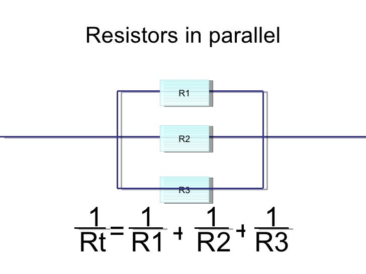
    1/Rt = 1/R1 + 1/R2 + 1/R3 + ..... 1/Rn.

    bi
    Originally posted by NROC View Post
    The value is right,

    The equation should just be 1/(1/R1 + 1/R2 + 1/R3)

    All the Best

    I really got these guys rattled the math you have down pat.


    Last edited by BroMikey; 07-17-2019, 09:08 PM.

    Leave a comment:


  • BroMikey
    replied
    @Bi is right magnets and hysteresis plus core loss at speed mitigate
    flux during start up. Right Bi

    You can get paid now Bi you have done your job.


    @Sky
    Transformer core leaflets of grain oriented steel are welded (Electrically)
    together to hold the block. Yes there are always some lose of perfection.

    Motor stator leaflets are drilled and is often stamped or hit like a dent
    (at which time each hole electrically contacts) All motors and transformers
    leaflets are electrically connected.

    Sounds like fun over there, keep me up to date on the 30awg coil.

    Leave a comment:


  • SkyWatcher
    replied
    Hi all, am going to set aside the big coil for the moment, it is possible it's not built properly.

    Am going to try the 51 strand-30awg. coil made from the previous smaller project.
    Will hook up 25 strands to start with, which is 1000 feet and see the difference.

    It is possible the 24awg. strands on the big coil, are not tight enough together, to give the required capacitance, maybe.

    Don't know what to say about turion's amp draw lowering with use of magnet to core cancelling at speed.
    It's obviously helping in some way we're not comprehending yet.
    Ideally, at speed, the magnet to core attraction incoming and outgoing phases would be perfectly equal.
    Though with eddy and hysteresis in the mix, things probably change that we are not realizing, regardless of my simple test, only one core with probably fairly low eddy and hysteresis, my core pieces are insulated, painted.
    I noticed in a video of turion's, it looked as though he used a grinder to flatten the core rod pieces and that would increase eddy currents by not keeping the rod pieces insulated electrically.
    Now amplify that by 12 coil cores and we can see that yes, he probably had some good eddys and hysteresis going.
    Though even with silicon steel laminates, 12 of those cores and the magnet neutralization would still lower amps quite a bit, probably.
    peace love light

    Leave a comment:


  • bistander
    replied
    Cogging again

    Originally posted by Turion
    ...{your edit}... Are you going to tell me it makes the hysteresis and eddy currents go away?
    What do you think? If you "neutralize" magnetism in the core(s), then there is no core flux, or changing flux, so there would be no eddy currents or hysteresis, right? But then there would be no generated voltage in the coil. So kind of makes the machine useless.

    The way I see you "magnetically neutralize" is to mount magnets on the rotor and stator remote form the coil core. So your neutralization magnets do not alter the flux in the core. Your neutralization magnets produce a counteracting force on the rotor at specific points which offsets the pull force from the main field magnets and cores. This appears effective to counteract cogging. But does nothing to alter the flux from the main field magnets through the core(s).

    Regards,

    bi

    Leave a comment:


  • bistander
    replied
    Cogging again

    It did not on your last test or on Sky's.

    And I do not, did not, claim that your "magnetic neutralization" does not work. It appears to mitigate cogging. But that is a non-factor to power required at speed.

    bi

    Leave a comment:


  • bistander
    replied
    Cogging again

    Originally posted by Turion
    ...
    And here's an interesting bit from an old video where I only had six of the 12 coils on the machine because the AMP draw with the coils UNLOADED was like 18-19 amps WITH JUST SIX COILS in place. Why so high when WITHOUT coils in place it is less that 12 amps if "cogging makes no difference at speed" as bi has claimed?? I'll give you a clue. It's because he doesn't know what he is talking about. Is that a big enough clue?
    https://youtu.be/A3DakXN-cR8
    Hi Turion,

    I assume by "coils" you mean coils with cores. So you have 12A draw on drive motor with no cores in place. And then with six cores in place you see 18-19A. Same RPM. You blame this on cogging. The increase in drive motor current (and power to turn the rotor) is NOT due to cogging. Cogging has negligible effect in power at speed. The Eddy current and hysteresis losses in the cores are responsible for the increased power needed to turn the rotor at speed.

    Regards,

    bi

    Leave a comment:


  • NROC
    replied
    The value is right,

    The equation should just be 1/(1/R1 + 1/R2 + 1/R3)

    All the Best

    Leave a comment:


  • bistander
    replied
    Not quite

    Originally posted by BroMikey View Post
    #23awg copper is 20ohms per 1000 feet for a single series connected
    circuit. This is for 1 and 3 such circuits are then all connected in parallel
    to each other giving a total

    Rt = 1/R1 + 1/R2 + 1/R3 = 6.667 ohms right again.
    It may be the correct value but your equation is wrong.

    1/Rt = 1/R1 + 1/R2 + 1/R3 + ..... 1/Rn.

    bi

    Leave a comment:


  • BroMikey
    replied
    #23awg copper is 20ohms per 1000 feet for a single series connected
    circuit. This is for 1 and 3 such circuits are then all connected in parallel
    to each other giving a total

    Rt = 1/R1 + 1/R2 + 1/R3 = 6.667 ohms right again.

    Leave a comment:


  • BroMikey
    replied
    Originally posted by dragon View Post
    Ok, so around 280 turns with approx 6 layers.... 3.2 ohm ea for each wire ( .135 ohm all in parallel - this looks nicer for efficiency ) ... 25+ ohms with 2240 turns total per series of 8.

    Just need open circuit voltage and short circuit current at running rpm....
    Let me think...........
    Dave fills a 3" dia spool so the average dia = 2" X 3.14= 6.25" per turn
    125'X 12" = 1500"/ 6.26" turns = 240T

    Not sure on spool length.

    Leave a comment:


  • dragon
    replied
    Ok, so around 280 turns with approx 6 layers.... 3.2 ohm ea for each wire ( .135 ohm all in parallel - this looks nicer for efficiency ) ... 25+ ohms with 2240 turns total per series of 8.

    Just need open circuit voltage and short circuit current at running rpm....

    Leave a comment:


  • BroMikey
    replied
    Originally posted by dragon View Post
    Thanks Turion, looking forward for the details

    Mikey, thanks for the info. I'm looking for the total turns of the bundle wound on the core so I can ascertain the total turns
    1" core and about a 6" length for 125'? Easy to calculate

    Leave a comment:


  • dragon
    replied
    Thanks Turion, looking forward for the details

    Mikey, thanks for the info. I'm looking for the total turns of the bundle wound on the core so I can ascertain the total turns once its wired in series. Also the open voltage, short circuit current, at what rpm and resistance of the coil ( maybe a resistance reading on one length of wire - the rest could be calculated ). I do understand the C core approach, very similar to a basic magneto alternator. Remember though, to much iron is much better than not enough when it comes to forming magnetic paths.

    Leave a comment:


  • BroMikey
    replied
    Originally posted by dragon View Post
    So thats how many turns on the core before you series the 8 together? And, your output voltage ( open circuit )... and your short circuit current if you have that as well... Ok, one more edit.... the resistance of the coil as it's used for the output ( 8 in series I'm assuming ).
    Thanks dragon for bringing me up to speed on your past winding schemes.
    Very interesting stuff indeed.

    Dave uses a 1" core and winds 24 strands in parallel onto it, some call
    litzed coils. Now with 24 wires going in and 24 wires going out he takes
    sets of 8 and this means he has 3 sets of 8. 3 X 8 = 24.

    8 wires or coils are wired up one after another or in series. Since each
    wire going in and out on his coil is 125" a piece he get 8 X 125 = 1000'
    This is Dave's favorite number of feet for his design that does not speed
    up nor slow down (more importantly) the rotor thus no affect on drive
    input.

    Since Dave has 3 sets of 8 coils he wires up in series whatever he gets
    out of one set of coils can be multiplied by 3X. The max rating for 23AWG
    wire when used as coils is I believe 700ma Dave stops at 500ma and
    having 3 channels or 3 sets of 8 coils he winds in series gives Dave
    a 1.5 amp or 1500ma output for a complete coil in his set up. 12 of
    these in total are used to decorate his little black box.

    I don't know anything about core material other than electrical steel
    except for what Dave said he tried. Dave's core rods work tho seem to
    be suffering some saturation effects long term.

    Do you understand why I am using a "C" core? Do you? You need to
    think about it. The "C" core (Not the material the shape) geometry
    is subject to both NORTH and SOUTH at the same time coming off
    the magnet. At TDC (Top Dead Center) the electrical winding magnetic
    energy having a certain polarity, reverses and both ends
    (Not just one end) of the "C" do a toggle . Flux goes back and forth or
    flux is traded back and forth almost a form of recycling.
    Last edited by BroMikey; 07-16-2019, 09:21 AM.

    Leave a comment:

Working...
X