This forum is preserved as a permanent archive. The community continues at eMedia Press.

Announcement

Collapse
No announcement yet.

Multifilar Generator Coil - Lenz delay Experiments

Collapse
X
 
  • Filter
  • Time
  • Show
Clear All
new posts

  • SkyWatcher
    replied
    Hi bromikey, thanks for the reply.
    Yes, this oscillator circuit is probably not best choice, a 555 timer pulsing the drive coil would be better.
    Though the point of these tests, is not to show a COP greater than 1.
    Just like turions setup, it would likely need many coil/cores to do so, that is, if we actually have a delayed lenz happening, with respect to the drive coil.
    And that is what these tests are about.

    Was testing the setup again and this was a better test.
    Kept the drive coil/core up close, in contact with the secondary coil/core, for the duration of the test.
    Whereas previously I started the oscillator and then brought it into contact with the secondary coil/core.
    This time also used identical led bulbs on flyback and output of secondary coil.
    The input without secondary coil led bulb load is .26 amps, when secondary load is connected, the bulb is very close to the same brightness as the flyback bulb and input drops to .25 amps.
    Will continue experimenting.
    peace love light

    Leave a comment:


  • BroMikey
    replied
    High frequencies spikes dancing on your
    LED bulb gives the illusion that extra energy may be
    present in your circuit delays or power lag can fool you similar to
    panning for fools gold. To verify extra energy is available a meter
    must be placed on the input as well as the output.

    Say for instance you put in .25amps or 250ma and the output gives
    you the same output then you have a 100 percent conversion efficiency
    and a COP of 1:1

    Just saying that the light took down the input by .03 amps or 30ma
    when powering up means little in terms of COP.

    Leave a comment:


  • SkyWatcher
    replied
    Hi bromikey, thanks for the reply, been busy cleaning the house of stuff we don't need.

    I hooked up another 120 vac, 6 watt led bulb to the separate, 26 strand secondary coil/core, the bulb lights and the input decreases from .26 amps, down to .23 amps.

    So, with the ability of the solid state oscillator coil/core to easily give higher frequencies, we can get the multifilar delay lenz coil to work, without the need for mechanical contraptions.
    peace love light

    Leave a comment:


  • BroMikey
    replied
    Originally posted by SkyWatcher View Post
    Hi bromikey, do you mean to try the device talked about in that thread?

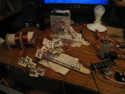
    Ok, since you are online at the moment, here is a pic of the setup.
    peace love light

    Goodness thats a bunch of wires. Yeah I think follow Turion with the
    solid state you know what do they call it? That U shaped metal with the
    locking bar across and the number of coil wound and connected the said
    way. Well that seems to be one way. I don't know what you are getting
    in the picture but it should be able to get a high high voltage so let it
    go up to as high as your wire can handle about 600v then string a group
    of bulbs in series.

    Thats what i think

    Leave a comment:


  • SkyWatcher
    replied
    Hi bromikey, do you mean to try the device talked about in that thread?

    Ok, since you are online at the moment, here is a pic of the setup.
    peace love light

    Leave a comment:


  • BroMikey
    replied
    Hey sky maybe Turion knows what might happen, he did some of those
    joule thief's, but me thinks the spike will destroy your bulb leds

    Ain't it the pits. Now then using 26 series strands for a secondary is a whole
    new ball game. Not sure what to try for kicks.

    Dave knows more than he lets on. Try ANOTHER BASIC FREE ENERGY DEVICE
    Last edited by BroMikey; 10-15-2019, 03:32 AM.

    Leave a comment:


  • SkyWatcher
    replied
    Hi bromikey, will post a pic tomorrow sometime, busy with some other things at the moment.

    The 120vac. 6 watt led bulb, is just placed across the drive coil diode flyback, so it protects the transistor a bit.

    Using a low ohm resistor across multifilar coil/core as load.

    As the pot. on the joule thief transistor base is varied, it does seem if the frequency is too low, the amp input does increase under load.

    Though when brought high enough, the input decreases under load and frequency increases and led bulb goes a little brighter.

    That seems similar to the mechanical version, maybe.
    peace love light

    Leave a comment:


  • BroMikey
    replied
    Sounds like 1 watt in and you can light an LED bulb? Maybe like
    the joule thief? Can you show the setup, I am lost to know what is
    being said.

    BTW I take back what i said, Thane only used a bifilar coil not a 26
    wire coil. Should be interesting. All in series? Humm..
    Got a vid or diagram?

    The amplifier drive was only for the BITOROID on steroids but it won't
    hurt to try it. The Bitt as we call it uses an alternation flux path to benefit
    from PF keeping the input the same. maybe you can do this with your
    setup? Hum...? Let me know.
    Last edited by BroMikey; 10-14-2019, 10:22 AM.

    Leave a comment:


  • SkyWatcher
    replied
    Hi all, have been testing the solid state multifilar coil generator.

    It seems the same effect may be manifesting.
    Using a drive coil/core that is using pulsed dc (joule thief style) and a 26 strand coil/core, in-line and in front of that, cores touching or with a small air gap, the small air gap gives a little more voltage.

    With the correct frequency range, using a low ohm resistor connected across series wired multifilar coil, the input amps decrease and an audible increase in oscillator frequency can be heard.
    Also have an led bulb off the drive coil, connected to flyback diode and that gets a little brighter at the same time.
    This test was only drawing around 1 watt.

    Will be testing this further and would also like to setup a flip flop drive circuit, to see if an AC drive will be any better.
    peace love light
    Last edited by SkyWatcher; 10-14-2019, 05:47 AM.

    Leave a comment:


  • lotec
    replied
    Originally posted by BroMikey View Post
    Did you try one of these? Remember you need power output also.
    Which one of the three can you demonstrate? Or have you done them
    all? Generators today can not be adjusted this way. Do you have such
    a motor generator? Or did you want me to run the test?

    Any data to support these possible solutions?

    Thanks in advance.
    HI BroMikey,
    It wasn't my intention to get anyones hopes up too high. I haven't tried or are able too demonstrate any of these. I was just running with the idea of an inductive load causing amperage and maybe ti's magnetic field to lag causing the rotor speedup, The idea of gradually lowering the inductance was just a method to adjust the timing, much like the vacuum advance on the old gasoline motors.

    I should have been more clear. The idea was intended to be a motor speed controller. I don't think that alot of power could be taken from it because of the inductive impedance that would be created. If it worked at all and the rotor speed could be accelerated to the point where the inductor could be bypassed and the coils are getting hot from being shorted to much, maybe then a restive load could be put across the coil,

    For it to work at all the think that the hardware would have to optimized for that and the coils would have to induct powerfully. It's a busy time of year for me and my current attempt at a machine is a while off. If you have a machine assembled and the idea interests you, you are welcome to try it. If you do, please share data.

    Regards

    Leave a comment:


  • BroMikey
    replied
    Originally posted by lotec View Post
    fast enough to bypass the inductor.

    Three possible ways to do this might be, use a large inductor with a removable core and gradually pull the core out until it is just an air coil, or have a multi-tapped inductor, or use the primary of of a transformer that has a higher inductance than the motor coils when unloaded, then gradually cancel out that inductance by increasing the load on the transformer.
    Did you try one of these? Remember you need power output also.
    Which one of the three can you demonstrate? Or have you done them
    all? Generators today can not be adjusted this way. Do you have such
    a motor generator? Or did you want me to run the test?

    Any data to support these possible solutions?

    Thanks in advance.
    Last edited by BroMikey; 09-25-2019, 09:37 AM.

    Leave a comment:


  • lotec
    replied
    Speed up with Indctive load.

    When speed up is achieved with an inductive load and has leveled out, it might be possible to make it continue to speed up by gradually lowering the inductance of the load until it is going fast enough to bypass the inductor.

    Three possible ways to do this might be, use a large inductor with a removable core and gradually pull the core out until it is just an air coil, or have a multi-tapped inductor, or use the primary of of a transformer that has a higher inductance than the motor coils when unloaded, then gradually cancel out that inductance by increasing the load on the transformer.

    Leave a comment:


  • BroMikey
    replied
    [VIDEO]https://www.youtube.com/watch?time_continue=187&v=AAJojRJXIV8[/VIDEO]

    Leave a comment:


  • Turion
    replied

    Leave a comment:


  • BroMikey
    replied
    Originally posted by Turion View Post

    If your goal is to bring down the RPM for speed up under load,
    you have 2 choices
    1. Add more magnets to the rotor.
    2. Add more strands of wire in parallel connected in series.
    Absolutely is a great goal because anytime we can bring down the RPM
    the longevity on the apparatus is increased for one thing. The other thing
    is that as RPM goes down the safety concerns or danger is reduced as
    parts wear down and begin to fail.

    RPM's of 3000-4000-5000 would require a higher degree of precision
    brought about by CNC machining, metallurgy, mechanical teams to
    construct for a smaller more powerful output for way less money.

    Did you ever use a high RPM generator for extended periods in the field
    to run saws and lights? Those poor machines run 3600 RPM's and
    degrade very rapidly. You know when she's gonna blow.

    On the other hand if you also had a chance to
    run an ONAN Generator at the same construction site you will
    understand the difference that RPM makes.

    As you work in the field using a screaming generator your nerves are
    constantly bombarded and you can tell that is diminishing day by day
    till one day you go buy another for fear you will be out of power.
    The other one still runs but you have to be ready.

    The Onan Gen runs for years and rarely fails, never making you wonder
    if it is going to hang in there. This is how I look at a slower moving rotor.
    The Onan runs at a crawl of 1800 rpm. Now you can rest easy.

    Bigger rotor, bigger winding, bigger engine for slow speeds, see below.


    https://www.youtube.com/watch?v=Yf2zP2UTK6A


    https://www.youtube.com/watch?v=MRJYAs5DOs8


    .................................................. ...............
    Last edited by BroMikey; 09-23-2019, 10:02 AM.

    Leave a comment:

Working...
X