
Hi Skywatcher,
Thanks for posting. I think that there is interesting things to be discovered with your current line of inquiry. In some ways it reminds me of Don Smith and his step up transformers and the mismatched time constants involved. When you first announced your intentions to explore the motionless version of the concept, my first thought was, how would the primary be engineered? When you said you were controlling the frequency and the duty cycle, then I think I was starting to get it.
If it turns out that the duty cycle was under 50%, then that is probably not a bad thing, I/m pretty sure that hard working iron needs some time to relax as well. I have held the view that the parasitic capacitance and the inductance of a coil are more intertwined, than what some people might think, due to feed back at a field level.
Anyhow, as far off the beaten track as my thoughts might be on the subject, I'm sure I'm not the only one out there who is interested in reading about what ever you want to share about that.
Thanks Sky, Turion and Bi.
Regards.
-
Hi all, been running experiments and thinking about different things to try.
I ditched the self oscillator, bifilar drive coil, as the trigger coil can be influenced by the magnetic flux from secondary multifilar coil, when loaded.
So, set up an astable 555 timer, with a regular transistor to drive the separate coil/core primary, though both the primary and secondary are on the same core, inline, facing each other.
It seems that if the duty cycle and frequency of the square wave pulse is set properly, the secondary coil can be loaded and even short circuited without affecting the input current, that the drive coil uses.
And while this is happening, a regular 6 watt led bulb is connected to a flyback diode, across the primary coil, bedini style.
And interestingly enough, that led bulb gets noticeably brighter when a load is placed across the secondary coils, bridge rectified output.
And when the secondary coils rectified output is short circuited, the led bulb across the drive coils flyback diode, gets even brighter, probably double the brightness.
Interesting results so far, It seems to me.
Anyone have any thoughts on this.
peace love light Last edited by SkyWatcher; 11-16-2019, 05:04 AM.
Leave a comment:
-
Hi bromikey, thanks for the reply.
Yes, will try that bucking method also, when I get the other coil setup.
In the meantime, I rewired the 26 strand coil, so it is now two, 13 strand coils wired in series.
Then placed them in parallel, to lower the voltage and also get more current, to charge a 12 volt sla battery.
The parallel coils are going into a full wave bridge and into the battery.
It is working well and the input current decreases while under the battery load.
Previously, with the mechanical version, using the bridge rectifier into certain loads, like a battery, caused the input current to increase.
That is assuming of course, that the multifilar coil is exhibiting a delayed lenz effect, which may be the cause of the decrease in input current under load.
peace love light
Leave a comment:
-
There is definitely something special about the multifilar coils whichOriginally posted by SkyWatcher View Post
John Bedini started showing 45 yrs ago I think sometime in the 70's.
Early radio work (1930's to 1960's) used alot of multi-strands
transformers and experimenters were catching on to many phenomena
including tubes with various gases in them.
My version can be increased on the output using sine wave to class
AB audio amplification common to everyone. Running the freq's up to
3000hz or more seems to be a target for power models.
Your new test could use a bucking connection for the 2 secondaries
that are multifilar.Leave a comment:
-
Hi bromikey, thanks for the reply.
Wow, that is a nice setup there and were you able to increase the output.
I made another experiment.
I removed the 26 strand secondary coil, temporarily from the core and slid a single strand coil onto the core.
This to see if the single strand secondary coil will function the same when loaded or shorted.
It does behave differently, when the single strand coil is shorted, the input current does increase.
Though with the previous test with the multistrand secondary coil, when shorted, the input current decreased the most.
The voltage with the single strand is not enough to light the led bulb, even though the turns are somewhat similar.
The next experiment will be with another secondary coil, on the other side of the input drive coil.
This test is to determine if the output will increase further and then observe the input current.
peace love light
Leave a comment:
-
Oh Okay I see what you are saying now. Yes that is true about bifilarOriginally posted by SkyWatcher View Post
coils sometime. When I tried it it was only 2 strands and it was the
bitoroid stuff where is had and extra path.
If you remember this picture? I was running way low ac volts like 10v
in off of one of my variacs. With the right load using tiny bulbs and or
high wattage ohmite resistors I was getting more out than in. But it was
on such a small scale that I stopped for awhile.
The core material is state of the art flybacks ganged up side by side.
The small coil was my drive coil and other two despite one's irregular
shape are identical in length, 2 strand. those 2 big bifilars had to be
connected to each other just right, one way doesn't work.
http://flyer.thenetteam.net/1BiTT3.jpgLast edited by BroMikey; 10-30-2019, 06:42 AM.Leave a comment:
-
Hi bromikey, thanks for replying.
Apparently we're having communication problems, I'm not following anyone's instructions.
I'm simply using the multifilar coil idea and making experiments, to see if the same effects shown in the mechanical version, can be done in the solid state, that is all.
So far, I'm seeing interesting results.
Because normally in a solid state transformer, (pulsed or alternating) if we induce current into a secondary coil, it always increases the input current.
Normally, it doesn't stay the same or go lower.
peace love light
Leave a comment:
-
Hi bromikey, thanks for the reply.
I did that previously and the flux transfer, even with a 1/4" thick piece of steel as the keeper, it still was not good enough to light the led bulb on the secondary coil.
Though with the core straightened and the coils right inline with each other, the led bulb is equal to the flyback led bulb.
Previously, when placing the coils with their own cores in each coil and in front of each other, the output was almost as good, but not quite equal.
I imagine with another multistrand coil, on the other side of the drive coil, the output would be even better, since the other side of the drive coil is not being used entirely.
peace love light
Leave a comment:
-
In order to get a good magnetic lock you must cut off the core endsOriginally posted by SkyWatcher View Post
so they are flat with a die grinder. Maybe if you do that it will work
better.
https://i.postimg.cc/ty8rs4Yn/New-U-shaped-core-for-solid-state-lenz-delay-transformer.jpgLeave a comment:
-
Hi all, I tested the u-core and could not get much current output from the secondary multistrand coil.
So, decided to straighten out the u-core and place the drive coil and secondary coil, directly next to each other on that core.
It works much better, the identical led bulb load, that is connected across the secondary coil, is lighted to the same brightness as the led bulb that is connected to the flyback diode, off the drive coil.
When the secondary coil is loaded, depending on the tuning of the potentiometer, the input current either stays the same, or lowers a little when loaded.
Though it never seems to increase when loaded, which is interesting.
peace love light
Leave a comment:
-
Hi bromikey, thanks for the reply, looked into the serps a little, not much information to find, though it sounds similar, maybe.
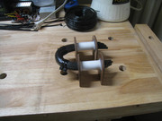
Decided to make another core, using the bailing wire, similar to the ed leedskalnin U shaped core.
This way, the efficiency will be higher and more tests can be carried out.
Here it is at the moment, still working on it.
peace love light
Leave a comment:
-
Disagree with what? I don't know the diagram, you have left me inOriginally posted by SkyWatcher View Post
the dark. Each pulse expands? Not static? Operates like a transformer
correct? Okay it is a pulsed transformer got it. Humm...Not sure I know
what you know or shall i say perceive your invention yet but I will.
As we all know the Tesla bifilar coil is meant to make HV and your coil
is no different than a pancake style winding. This was pointed out in the
patents. In the patent high voltages are produced and we have all heard
the formula's how energy is squared at HV.
So pulsing and delaying seems to have it's effects like with the serps or
the MIT and so on where AC at 60hz is not solely the only energy input.
Very interesting work, keep me posted on any results.

Leave a comment:
-
Hi bromikey, thanks for the reply.
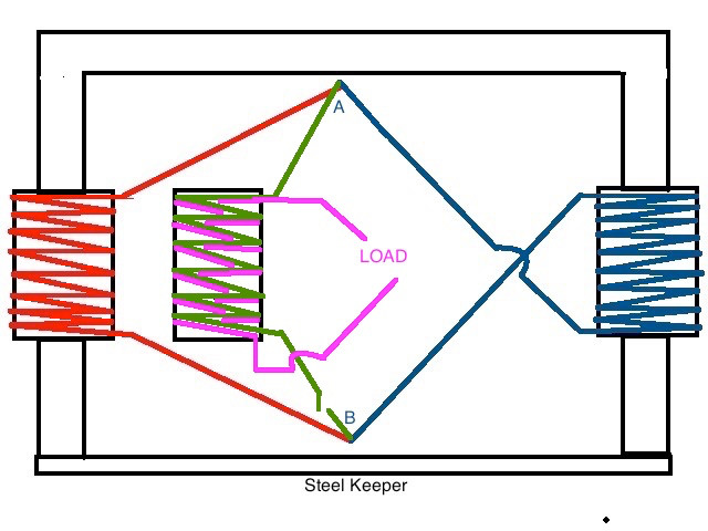
Sorry it's not clear, when I finish a few more tests I'll post the circuit drawing as it is.
As far as I'm aware, it is not a static field, it is an expanding and contracting magnetic field.
So, it is similar to the mechanical version.
By the time the drive coil shuts off, (with proper coil capacitance and frequency in secondary multifilar coil), then the secondary coil releases it's magnentic field and powers the load, without interfering or opposing the pulse input of the drive coil.
This then causes no increase in amperage and may even cause a decrease of each input pulse, very much like the mechanical version.
At least that's my thinking on this, you're of course free to disagree.
peace love light
Leave a comment:
-
Oh so you have 2 bulb, I did not know the circuit. First bulb 260ma
then 30ma went to second bulb. I am working in the dark as to how
exactly the circuit is laid out. But hey just say it with no proof

Well that is the voice of the skeptic. I don't know what you know so
tis near impossible for me to comment correctly without more details
Happy testing.
After all it is a Tesla coil right? Ya know a bi-filar and many more and
what did Tesla get from his bifilar coil? Humm..?? What?
Tesla got HIGH VOLTAGE 50v per turn or something outlandishly high
compared to a regular coil. keep ringing the bell at HV connecting
5 bulbs in series. Then we will have an answer. Lenz delay? For what?
Delayed what for what? Why would you need a delay for a static field.
I am not sure I understand the reasons you test your transformer expecting
a delay then what a delay does. Or how a delay might affect the circuit
Leave a comment:
Leave a comment: