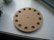
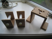
This forum is preserved as a permanent archive. The community continues at eMedia Press.

Announcement

Collapse
No announcement yet.

Multifilar Generator Coil - Lenz delay Experiments

Collapse
X
 
  • Filter
  • Time
  • Show
Clear All
new posts

  • BroMikey
    replied
    Originally posted by SkyWatcher View Post
    Hi all, finished securing all the magnet spacers in the rotor.
    peace love light

    I just saw a guy on youtube show a rotor made of this material
    explode and shatter 3-4 magnets on one end came off due to these
    light weight press boards weaknesses.

    I can't remember the letters designated for his board and brand.
    Your magnets are much lighter than his was. Glad you got a shield.

    The guy I saw in the video did not have a shield so I never heard what
    the magnets actually hit you know like a lamp or a window. No
    children allowed.

    Standing a magnet up on it's edge like a silver dollar to put glue on that
    tiny surface area is not as good as laying a drum on it's side to put glue
    on the huge amount of area. Same pull force just more gluing area and
    not just gluing are but also the area where force thru centrifugal that
    will hold the magnet in place.

    You need not reply. This is only a repeat of an old post pointing out what
    no one else has stated because up until now only coin geometry magnets
    have been suggested since they only cost 20 cents a piece while the drum
    magnets are way more expensive coming in at $1.99


    Last edited by BroMikey; 05-27-2019, 09:39 PM.

    Leave a comment:


  • SkyWatcher
    replied
    Hi all, finished securing all the magnet spacers in the rotor.
    peace love light

    Edit: Also, I chucked it in a drill and secured a metal file to the work bench. Then spun it up on the file and was able to get the rotor rounded fairly well, seems very true with regard to rotor edge.

    Last edited by SkyWatcher; 05-27-2019, 09:17 PM.

    Leave a comment:


  • BroMikey
    replied
    Sounds good to me, never tried that one so let me know.

    Leave a comment:


  • SkyWatcher
    replied
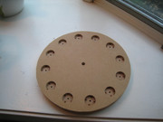
    Hi bromikey, thanks for the helpful information.

    Though as I said previously, I used a cad print out and taped that to the wood.

    Then used a sharp metal punch at the crosshair marks that are printed, through the paper and into the wood as my pre-pilot hole.

    Then used fostner drill bits for all the holes, as they have a nice central point on those bits.

    It should be very close, if any issues, I'm sure they can be worked out as you are saying.
    peace love light

    Leave a comment:


  • BroMikey
    replied
    Originally posted by SkyWatcher View Post
    the shaft hole is probably less critical, though will be done.
    You are going to be surprised to see how important it is to do that.

    The point made by a pencil lead is as wide as 5 thousandth and it is
    so easy to be off 10-20 thousands. What I like to do is to do the rough
    cut circle then after I am sure the dot in the center is close I drill it.

    After that I drill a bigger hole to put my shaft and hub into. Then into the
    drill press to check for roundness WITH a pencil or scribe. Even drawing
    with a compass after the hole the size of the shaft is drilled requires
    a spacer to do the drawing on the outer edge.

    I instead use a small ruler size board drilling a shaft hole in one end and
    a 1/16" hole on the other end where I want to make my mark. This is
    much more accurate than a compass. It is a way to strike a circular
    line. I use 3 holes to make circles about 1/8" apart going inward
    so I have something to visualize. Its a homemade compass that rotates
    right off the shaft. Then strike a line right on the edge (drill tiny holes)
    where you THINK the circle is perfect. Boing boing it's always off a tiny.

    You are welcome, my expertise (on a good day) is mechanical schemes

    3000rpm will be no trouble at all. Smooth a silk. The magnet holes are
    not as critical due to the weight of each being so close to the next (I hope)

    Unless it is out by 1/8" then I have been known to move the center hole
    and shim

    https://etc.usf.edu/clipart/77300/77340/77340_circle_crve_md.gif
    Last edited by BroMikey; 05-25-2019, 06:58 AM.

    Leave a comment:


  • alexelectric
    replied
    Originally posted by Turion
    The machine I recommended (which I have also built and am putting back together at this time) is all N magnets out on the rotor. For EXACTLY the reason Bro Mikey talks about. When you are using a horizontal rotor with magnets on the rotor edge, when a magnet is aligned in attraction with a coil, the magnet directly across from it is aligned with an adjustable magnet on the stator. They cancel each other out. In a vertical rotor, that's magnets on the face of the rotor instead of the edge (so it can have a coil on each side of the rotor) wen the magnet is aligned with the two coils, the magnet opposite it on the rotor is aligned BETWEEN two adjustable magnets that match the face of the magnet aligned to them in repulsion. It will not put out as much as my big machine because it is only 10 coil instead of 12 and does not have as many magnets on the rotor, nor are they as thick. But when I get it back up and running it will STILL prove my point. I know some people are going to whine because it doesn’t put out 2,000 watts, but let them. It is also WAY less expensive to build than my big machine for a number of reasons. Size, number of magnets, etc. So it is THIS machine I have chosen to share for replication.

    My BIG machine has N/S magnets on the rotors and 12 coils. But the rotor is larger in diameter by 3 inches and has a second set of magnets out closer to the rim. Each time one of the primary magnets centers between two coils in attraction to both, these secondary magnets center between two magnets on the stator in repulsion. The N side of the magnet is aligned with an N magnet on the stator and the S side of the magnet is aligned with an S magnet on the stator. The stator magnets are adjustable on the big machine just like on the small machine, but I made MISTAKES building the big machine that I corrected when I built the smaller one. The big machine used square magnets that rode in square plastic tubing and the little magnet holder that was adjusted in and out was complex and did not work well. I went to round magnets in pvc pipe for the small machine and that eliminated the magnet holder complexity. Live and learn. It was also CHEAPER, which is always good.

    At speed I see no difference in INDIVIDUAL coil output between the two machines, but the number of magnets on the rotor makes a difference as does the thickness of the rotor magnets. One just has more coils and stronger magnets. It USED to have weaker magnets and that is when I compared the output of the coils. Right now, the bigger machine definitely gets MORE out of the coils.

    Which brings me to another thought. At SOME point the core is absorbing all the flux it can accept, so the coil will put out NO MORE electricity no matter HOW big or thick the magnets are. I don't know what that point IS.

    as a side note: I have an entire box that is probably 18 inches square built out of 1 x 6's holding all of the different rotors I have tried on these machines to get the one I believe outputs the most for the situation. They each have a piece of 3/4 plywood between them so that I can get them apart because the all want to stick together. Some of them are only 1/4 inch thick with a single magnet pressed in, and some have magnets pressed in from both sides. Some are missing some of the magnets because they got pulled out for the NEXT rotor. I would be happy to send ANYONE one of my old rotors so they can experiment if they are willing to pay the cost of shipping up front. I am really tired of people promising me they would pay for shipping and then they get what I sent them for FREE and never paid my shipping costs. I can't tell you HOW many times that has happened, and I don't mind giving stuff away for free or I wouldn't OFFER it, but it is the principal of the thing when people make promises they don't keep.
    greetings friends we can communicate by mail to see the cost of shipping, I'm interested in your proposal and thanks

    Leave a comment:


  • SkyWatcher
    replied
    Hi bromikey, thanks for the positive and helpful reply.

    I figured it was more important to spot the holes for the shaft and magnet holes, and the cad print out was used for that.
    The roundness of the rotor relative to the shaft hole is probably less critical, though will be done.

    Now, if I was placing the magnets in the edge of the rotor, then the method you describe would be best.
    peace love light

    Leave a comment:


  • BroMikey
    replied
    Originally posted by SkyWatcher View Post
    Hi bromikey, thanks for the kind words.

    Been working on the rotor today, still need to true up the perimeter and make the spacer discs.

    I used cad and printed the drawing.
    Then used a pointed metal punch, to punch pilot marker holes through the paper and into the wood.
    peace love light

    You want to know what I do when I drill up holes on my rotors? First I
    cut the circle and center hole as close as I can. Then I chuck up to a drill
    press and turn it to see how far out of round it is and then shave al
    little off as needed. That way there is no jumping later, then I lay my
    pattern out for the magnet holes.

    Sure is a pretty cut you have there, hope she don't jump.

    You can still shave a little off and it won't hurt a thing. Make sure you
    use the shaft and hub going into the genny. Sometimes I us a bearing
    to hold the shaft at the bottom while turning it in the drill press, if it's
    really big.
    Last edited by BroMikey; 05-25-2019, 02:28 AM.

    Leave a comment:


  • SkyWatcher
    replied
    Hi bromikey, thanks for the kind words.

    Been working on the rotor today, still need to true up the perimeter and make the spacer discs.

    I used cad and printed the drawing.
    Then used a pointed metal punch, to punch pilot marker holes through the paper and into the wood.
    peace love light

    Last edited by SkyWatcher; 05-25-2019, 12:31 AM.

    Leave a comment:


  • BroMikey
    replied
    HEY Sky good to see you back

    Leave a comment:


  • SkyWatcher
    replied
    Hi all, back from vacation.

    I was doodling in the hotel and came up with a rotor solution I think.

    So the rotor will be 3/4" thick and all 12 magnet holes will be drilled clean through.
    Then, I thought of using a small disc, using same material as rotor, same diameter as magnet hole and 1/4" thick.
    This disc will act as the spacer between magnets, to get them to attract to each other.

    Then, some small holes are drilled around the edge of the disc, 1/16" inch deep and out the side of the disc, to accomodate super glue.

    The holes will take the glue and not get in the way of the neo magnets that will be placed on each side of the disc.
    Will be working on rotor soon.
    peace love light

    Leave a comment:


  • BroMikey
    replied
    Originally posted by SkyWatcher View Post
    got it at menards in plumbing section.
    peace love light
    Been doin yer homework I see. Some of that is even thinner, perfect.
    I use that stuff myself on occasion when I did the Bedini coils. Good
    choice.

    Nothing wrong with bushing up of details. For instance my latest coil
    "C" core to magnet tolerance using only a 9lb magnet still offers a good
    amount of pull with a 1/16" gap. May be 5lbs guessing.

    See you next week.

    Leave a comment:


  • SkyWatcher
    replied
    Hi bromikey, thanks.
    Yes, thought it needed beefier screws.
    The pvc pipe is 1/16" wall thickness.
    It was an 8 foot length if I remember correctly and came with a metal fitting on the end, It may have been used for hot tubs or something, not sure, got it at menards in plumbing section.
    peace love light

    Leave a comment:


  • BroMikey
    replied
    Remember that the spool thickness where the wire winding goes
    around the core material needs to be 1/16" and no greater.

    Most of the pvc pipe can be much bigger depending the schedule.

    The wood looks great, nice big screws.


    SCH40 for 1" is a .133 wall thickness over twice 1\6"

    Last edited by BroMikey; 05-19-2019, 02:53 AM.

    Leave a comment:


  • SkyWatcher
    replied
    Hi all, Hi bromikey, thanks for the encouraging words.
    Yes, pulsed motor might come in handy with these experiments.

    Well, have been working on the parts for ths project, will be away for a few days, when I get back, will start work on the rotor.
    peace love light

    Leave a comment:

Working...
X