This forum is preserved as a permanent archive. The community continues at eMedia Press.

Announcement

Collapse
No announcement yet.

Multifilar Generator Coil - Lenz delay Experiments

Collapse
X
 
  • Filter
  • Time
  • Show
Clear All
new posts

  • BroMikey
    replied
    Here are a few more examples. Think about it? Eventually you will
    understand why that this is the way it is done in factories today.

    Generator rotors with strong magnets. Old news.
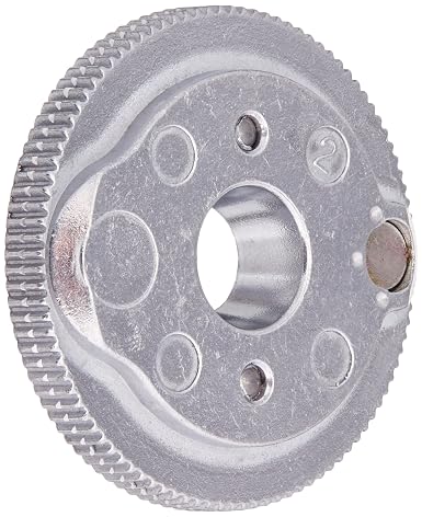


    Yamaha


    https://x.cloudsdata.net/6f/images/products/large/5c6c2208ca2ec_IMG20190219163154.jpg

    Buy one already made

    https://unitedexpressdist.3dcartstores.com/150cc-125cc-Scooter-Moped-Magneto-Flywheel-Stator-GY6-8-Magnet-152QMI_p_2105.html

    God awful vibration and super RPM's epoxied magnets.

    https://i.ytimg.com/vi/6HBBQWjT0Os/maxresdefault.jpg
    Last edited by BroMikey; 05-11-2019, 03:49 AM.

    Leave a comment:


  • BroMikey
    replied
    So everyone understands, I am not talking about sticking a magnet
    on the side of a pop bottle with epoxy. Look at how it's done
    mechanically first and know that the epoxy does very little yet it is
    there. Not just any type you decide to try, it is special stuff, use it.

    Keep in mind these rotor run 5000-6000rpms, the big pic is a for a
    motorcycle generator. Press fit epoxied but that doesn't mean the
    epoxy is the only thing holding it. The magnet holds itself in also.

    https://thumpertalk.com/uploads/monthly_03_2016/post-463607-0-82547500-1457076285.jpg

    https://thumpertalk.com/applications/core/interface/imageproxy/imageproxy.php?img=http://i1376.photobucket.com/albums/ah12/gsuarezlecuona/Husqvarna%2520TE610e%25201998/IMG_20150408_193936_zpsum8imq1a.jpg&key=5b6b3727f9 b118f8dfe6ba14db2d17e6e101d45a59b918f16777a0e4323e 11db


    Last edited by BroMikey; 05-11-2019, 03:25 AM.

    Leave a comment:


  • SkyWatcher
    replied
    Hi turion, thanks for the offer and sharing the video, though I need to build this myself, so I can learn more and gain more experience.

    I think I will design the rotor like the single plastic one you showed, with the material left between the 2 magnets, so they help keep each other in.

    Also, could always put a thin, but strong enough lexan laminate over the entire side of each rotor and secure with screws, to help retain the magnets.

    Yes, I realize, especially now that I've started recovering my epoxied neo magnets from a previous rotor project, how brittle epoxy is and under stress, not a good idea.

    Good thing those magnet stacks were attached to a ferromagnetic rod, or they probably would have let loose.

    So I'm thankful you guys are pointing these things out.
    peace love light

    Leave a comment:


  • BroMikey
    replied
    You are right, forgot that one and have little knowledge. All north's?
    Okay. I'll have to think about that a while.

    The thing about the shields is that counterbalancing magnets and rotor
    magnet might reach over a 3" span while magnet to core interact at close proximity say 1" range and even closer if shields are used.. In order to
    lower the drive input magnets to magnets and magnets to core material
    must be equal, easy to say and hard to do.

    Controlling stray fields is done with shielding even with all north's you
    want separation and the virtual south should still be there.

    If you have many magnets around a rotor LIKE THANE DOES you have
    magnets that are as close as 1/4" apart, without a shield your rotor
    will fail. Thanks for being so understanding.

    I thought aluminum was bad? Well I heard that on youtube where
    someone showed that it just didn't work. Do you have any aluminum
    rotors yet?

    You need help to perfect your system, too bad everyone has jumped
    ship and the burden now falls on you. Everyone is weak in one area or
    the other so we need to work together. Where is the help?


    Leave a comment:


  • BroMikey
    replied
    Common sense teaches that to properly build a rotor with magnets
    shielding / holders, magnet holders MUST be used. I have spoken till
    I am blue in the face about common sense/practical mechanical.
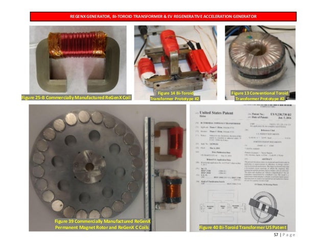
    I will hold back no punches. THANE HEINZ? Do you acknowledge his
    work? Do you see his rotors? Do you read patents concerning power
    generation for marine installations? We if you did like I am seeing
    you would know that shielding / holders limit the magnetic field from
    one pole overlapping the next pole.

    Do I need to draw a picture of a rotor with magnets on it doing a
    field visual of overlapping magnetism? Do I? You know me, I will.

    I am discussing refinement and practical applications not proof of
    concept. I want it to run so it does not tear itself to ribbons or burn
    up with heat.

    Magnets having shielding / holders are mounted with special press fit
    rubberized epoxy formulas. The holder centralizes the magnet inside.

    In other words my magnets on my bench for my project show that the
    shielding/covers/holder keep the magnet from coming out, they are held
    by the field itself. The magnet keeps itself to a degree.

    Yes I have it on my bench and no I am not talking speculation. It might
    help if your read my posts in your busy day. Anyway I am warned now
    about giving advice.

    Another thing (MY OPINION) you run 3000rpm's using plastic rotors you
    are going to be killed eventually or kill someone with a magnet. This is
    not a game of who is better this is about common sense staying in
    one piece.

    Okay lets take it from the top.

    #1 All commercially grown rotors use some form of a metallic substance
    to ensure structural integrity for tolerance

    #2 Magnets not only need holders to help retain their position but
    the same is a magnetic shield limiting magnetic interference. Shields
    push the field out front where the core is not permitting the field to
    reach over several inches to the adjacent pole not intended to be
    engaged.

    I have stressed this before, common mechanical sense, probably way
    over the heads of those not considering. Look at Thane Heinz rotors.

    Reject my offering go ahead, to your own peril.

    Now does anyone what a suggestion how to hold magnets more tightly?
    I guess not.


    Many other pictures of this rotor are on this site put here by one of
    Thanes past machinists. These many pictures show shielding cylinders
    around the magnets.

    I have shields and I use metal rotor, I have them here on my bench.
    Yes they work just as well as plastic. I have plastic rotors on my bench.

    So my experience is what i am speaking about. Personally I think you
    have to be crazy to run a plastic rotor up to 3000rpm - 4000rpm
    Insane.

    Plastic cracks, plastic can not stand the pounding, plastic can not
    take the vibration. Plastic is a joke and unsuitable for long term
    practical use in high quality machines.

    The shielding eliminates the problems where a metal rotor bleeds of flux.

    No commercially available electric car motors use plastic rotors and
    rightfully so. Electric motor engineering is not totally without merit.

    Thank you for your time. You better listen to me.
    Last edited by BroMikey; 05-10-2019, 10:31 PM.

    Leave a comment:


  • viomarmi22
    replied
    I bought 40 pieces. of this type of neodymium magnets for the construction of a rotor with halbach array.

    https://www.aliexpress.com/item/2-pc...34934c4dlqeYUy
    Attached Files

    Leave a comment:


  • SkyWatcher
    replied
    Hi all, Hi bromikey, yes I was looking at thanes more recent stuff, c-core is too difficult and costly, so I will just put coil/cores on both sides of rotor.
    I'm going to make it as simple as I can imagine it, similar to that large replication of bedinis free energy device, on that trailer, though without the flywheel and of course, not that big.

    Still recovering a bit from being sick, so not going full force at this just yet, though I AM planning it out in my mind, for when my body is ready to rock.
    peace love light

    Leave a comment:


  • BroMikey
    replied
    Hurry up Turion yer gittin old Your first model is about the mechanical
    level of the average guy. Tho scary it works.

    Good choice Sky we trust your preference. You have all the advantages
    by listening to our past blunders. Everybody makes mistakes.

    okay here is what is rolling around. Thane use to use those magnets
    with holes in them plus the easy shields you can pick up at the time
    but the hole makes a mess of the field, strong is not everything.

    Thane did a lot of video showing speed up or what he calls his RegenX
    coils before we found out he was running 1/4" gaps. Any tighter and
    the rotor bearing play and the rotor flex becomes an issue for tolerance.

    When Thane finally emerged with his closer gaps he had to use "C" cores
    to be practical. Unless you are going to follow Turion where he places
    another coil on the other side to balance out the stress.

    Vertical rotors need magnets long enough to come out on both sides.
    Big bearings, big shaft and quarter inch gaps will permit some runtime
    without magnets getting loose.

    So when you think about a coil remember it takes two coils for each
    magnetic pole.

    Also Thanes latest coils are not that big on the "C" cores probably don't
    need such big ones with the larger dia rotor on the back end of that
    E-Bike plus the tight gaps help. But what I want to say is that he gives
    the output of his new coils. He is running 36-48vdc back to the drive
    batteries (somewhere there) and intermittently 10amps each but targets
    5amps running back to the pack. 10 coil packs gives him 50amps back
    to his drive batteries so while recharging is taking place as he drives
    the power to drive the back wheel increases with each engaged coil.

    So Turion is getting 195w and Thane is getting about the same per coil.
    I find that very interesting.

    ......................................
    Last edited by BroMikey; 05-10-2019, 09:34 AM.

    Leave a comment:


  • SkyWatcher
    replied
    Hi bromikey, well that settles it then, I'm making it a vertical rotor, I have built many vertical rotor devices previously, so I'm not too shabby at it.
    This way, will be easier to get tighter tolerances.

    Hi turion, thanks for sharing.
    Yes, even this little test model took some hours, though It was worth it, for what it showed.
    peace love light

    Leave a comment:


  • BroMikey
    replied
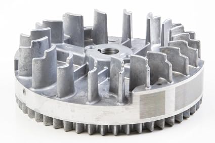
    Every yardman has seen a magneto on a lawnmower, gokart, tiller,
    minibike or a snowblower. This is the correct format. Embedded in the
    face of this fan/flywheel/rotor is a horseshoe or arced magnet.

    Air gaps are 10-20-30 thousandths depending on the motor

    1/16" = 62 thousandths

    Properly done the core must be cut in an arc as well, to meet the surface
    of the magnets.

    Last edited by BroMikey; 05-10-2019, 02:41 AM.

    Leave a comment:


  • BroMikey
    replied
    Originally posted by SkyWatcher View Post
    Hi turion, thanks for the tips, wondering how you will trigger what looks like motor coil placements, since the rotor has alternating poles.
    That's odd that you can only get 5/16" gap,

    Yes, I'm going with the horizontal rotor,
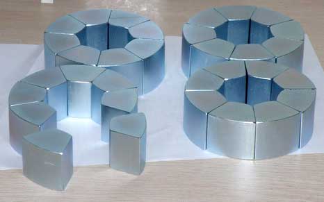
    Think about this picture of rotor magnets that you will need then
    The outer edge must be machined to keep a constant gap, other wise
    you can't work in thousandths of an inch fitting square pegs into
    round holes. If this does not help you to understand Turion's
    recommendation I can continue. Trust me it will sink in.


    You will have to do better than this.See?


    Take your time, there is more here than many may think, it will take
    effort to hold back long enough to count up all of the needed order for
    excellent success. Unless you want to throw it away later and start all
    over again. A square magnets around a circle? Hummm...
    Last edited by BroMikey; 05-09-2019, 09:41 PM.

    Leave a comment:


  • Pot head
    replied
    Hello all, Turion mentioned square coils,...maybe a triangular pattern that recedes or increases its points as the coil goes forward?
    Example: triangle coil placed over triangle coil and then it is advanced or retarded from first coils starting point, then another in the same pattern.
    First coil is at 12 noon, second coil starts at 1pm and third starts at 2pm,...etc.
    Hmmm.

    Leave a comment:


  • SkyWatcher
    replied
    Hi turion, thanks for the tips, wondering how you will trigger what looks like motor coil placements, since the rotor has alternating poles.
    That's odd that you can only get 5/16" gap, with my 1" diameter neos and this 4" diameter rotor, I can get it to 1/8" gap, just sitting there and when the corners of the magnet pass the core edge, it is closer to 1/16" gap.

    Yes, I'm going with the horizontal rotor, only because the vertical rotor needs another coil on other side of magnet or 180 degrees from it, to balance the forces, or the rotor goes wonky.

    People building this smaller model is infinitly more helpful to the cause, compared to nobody building it turion.
    peace love light

    Edit: what's the diameter of that rotor turion, looks like 8-10"
    Last edited by SkyWatcher; 05-09-2019, 06:17 PM.

    Leave a comment:


  • lotec
    replied
    Gentlemen Start your engines.

    Personally I think the motor coils are where it's at. I'm speculating again, but trying to take too much power from gen coils used as motor coils, is a bit like putting a banana in the tail pipe of a carbon burner. It seems paradoxical, but the universe is a big place, and contrary to what we are told to believe, there should be enough for everyone.

    I'm thinking of an old legend of the Fords Model T's magneto, being used as a 40 horse power self running electric motor. Motors are just about the timing, so when that window of opportunity is open. what can be done? So they had good quality iron, hysteresis, copper wires, spark gaps, and condensers.

    Bro Mikeys idea of having a clutch is great ( probably not that easy), but the starter motor can be disengaged when it starts to become a drag.

    I'm going to stop speculating now before I become too much of a drag.

    cheers.

    Leave a comment:


  • BroMikey
    replied
    Originally posted by Turion
    .

    Originally posted by Turion
    The standard coil bobbin I am using holds
    3,000 feet of #23 when FULL. That gives me about 130 volts at
    1.5 amps per coil with my rotor running at 2800 rpm
    .


    https://www.ebay.com/p/500w-24v-Electric-Motor-With-Bracket-Scooter-Bike-Go-kart-MINIBIKE-My1020/892033303?iid=283420548161


    Lets see that is

    Drive input 24vdc X 12amps = 288watts

    Speed up Generator (single) coils output 130vac X 1.5 amps = 195watts

    Multiple Speed up type generator coils (12 coils) 12 X 195w = 2340 watt

    yeah I'de say that is better than COP > 1 so lets find the COP Okay?

    That would be as follows 288w / 2340w = 8+ or COP 8

    Now also consider Turion's past statements where the drive input of

    288watts can be recycled or some can be recovered while running using

    "THE THREE BATTER CIRCUIT" and from what I recall he recovers 50%
    of 288w so now the COP doubles.

    Dave has gotten even higher than that but COP 16 is far beyond my
    wildest dreams.

    Correct me if I made an error since I am recalling data from past threads.


    .........................................
    Last edited by BroMikey; 05-09-2019, 09:54 AM.

    Leave a comment:

Working...
X