
Attached Files
-
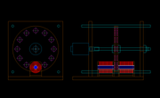
Hi all, this is the design I have so far, the parts to connect the motor shaft will have to be devised still, though it's a start.
The counter balancing magnets can still be applied and more coils can be added, they're just not shown at the moment.
peace love light
Leave a comment:
-
Hi all, been doing the mothers day thing today.
Though I did get some time put in working on a design for vertical rotor.
The only tricky part, is that I need to get parts to make a coupler for the 5/16" motor shaft, because I don't think an arbor on the motor shaft, with rotor secured at arbor, will be very stable, plus making room for coil/cores.
So I'm leaning towards flange bearings with a separate shaft, then a coupler to motor, two sidewall supports, which bearings mount to, adjustable with threaded rod.
The rotor will be three, 1/4" thick pieces, glued together, the center rotor piece will be solid, to keep things uniform and balanced and to allow each 1/4" thick magnet to attract to each other, through that center rotor section.
Using cad, 10" diameter rotor with 12 magnets seems to work well.
I'm not sure what the bickering is about, though In my eyes, this is not a competition. Cooperation is just that, cooperation.
I'm not going to preach here, nor am I judging anyone, though the honest truth is, to be offended is a choice.
This is something I have come to realize and have put effort into taming whatever it is that seems to cause us to be offended, it really is like those old cartoons with some kind of entity on one shoulder and one on the other, we can choose which one we feed or neither and just stay neutral.
peace love light
Leave a comment:
-
I finally got under your skin? I deserve whatever I get. Anyway you
are the chief cook and bottle washer who has led the way and is the
final authority. The point is someone with a 3D printer and the right
magnets could eliminate the cogging completely. I am not even close
to eliminating the cogging (OR DRAG YOUR WORD SWITCH) and as
you have just now confessed have not eliminated ALL of the drag either.
Mad Mack taught that by moving a magnet rotor past forks you could
take measurements in LBS to learn with. Shielding around magnets
helps to give the operator some adjusting room as shields can be slid
back and forth changing the fields in many ways. One way is to limit
the peripheral field.
Anyway Mad mack was right, it is the little things that change the game.
You gave yourself and will always continue to do that, it is part of
your teacher gift. Remember the students who always went out of their
way to get under your skin?
The drag can be further reduced, the bench shows this, my bench work
has value, I trust what i see on the bench..Last edited by BroMikey; 05-13-2019, 08:21 AM.Leave a comment:
-
Turion, Friend your work is very valuable, and if you are valued by many, and have experience and knowledge,
you continue with your experiments and demonstrations, your comments and presentations, I learn a lot from you.
of the comments other users, goes of all kinds, and you must be prepared to take things slowly, do not let discourage invade, why you lose, and what I have seen and read of many of your prototypes are a sample of your talent and knowledge, some people will not value it, and others will,
in this forum there is everyone, those who want to learn, those who build and share, those who doubt the projects (it is valid if they provide their arguments well founded), the debate and constructive criticism helps to be closer to the truth .
my respects and admiration for you
. I saw how he defends his ideas and proposals, in the other sections of the forum you have contributed many projects, my admiration,
go ahead, with the generator and continue sharing it, I am interested in building a small replica, it is very interesting
Do not be discouraged, adversity makes you great
see you soonLeave a comment:
-
It is nearly impossible to show a rotor that does not cog. What I amOriginally posted by Turion
seeing in your videos is that the project is nothing like I envisioned
from the many posts.
video's say it all. No balanced or non cogging rotor I was actually
hoping to see a free wheeling rotor in your set up, yet each time
this is not shown due to problems? Half assembled?
Hum...... Dang I wished I could see that machine with zero cog.
Hard to do.
One thing important for those trying to use the counterbalancing
magnets, use a smaller magnet than the rotor magnet. Distance can
not solve all the problems with balancing.
It is possible I know because I am getting closer.Leave a comment:
-
Awesome Dave, dang, why didn't i think of thatOriginally posted by TurionLeave a comment:
-
very good information, all the help of this experienced user is appreciated.Originally posted by Turion
a very kind request, can through schemes show what you say, to have more clarity than what was commented, read and read and some things I do not understand, with all respect for your knowledge,Leave a comment:
-
Hi all, thanks for sharing the good information.
It's time to fire up the cad software and start working on a design.
peace love light
Leave a comment:
-
Yes I can answer that. To use a counter balancing magnet on theOriginally posted by Netica View Post
opposite side from the coil from the rotor they must all be one way
(north in this case) to do it.
Turion has told us this for years, but it's okay, I'll help out on repeats
if that is okay?Leave a comment:
-
Hi Turion,
Its good to read the info you post to help people, thanks for all your help.
From what I can learn your rotors have all the same poles on each side of the rotor. I am just wondering if you have ever tried to run north, south, north, south, on the same side as well. And if you tried it, if you found any difference in the way the generator would run.
I was wondering if you chose all magnet poles being the same on each side of the rotor for any particular reason?
ThanksLeave a comment:
-
Hi bromikey, thanks for sharing the information.
Hi turion, thanks for sharing.
I see what you mean, the narrow magnet would reach the center of the core (TDC) ,much quicker for the same rpm, or I mean it has less distance to travel to TDC once the core interaction starts.
Of course, that would not give a good power sweep of the coil, without the magnet height, then again, with a bumped out core, it might not matter as much.
Sounds like you've built it and tested it, would like to see pics of that.
I don't have any small diameter neo's on hand, just the 1" diameter, though I could get 5/16" or 7/16" diameter disc neo's.
peace love light
Edit: Also, I created this thread for experiments, to see if I could get the true effect and I have.
Not for how low can we go, that was bromikey's ideas, which are fine.
Now I would like to try and make some useful juice and keep the rpm's lower if possible.Last edited by SkyWatcher; 05-12-2019, 12:55 AM.Leave a comment:
-
Does the core size stay the same in this quiz? Say a 3/4" core used for
both magnets? If I knew that then I could look more at duration.
Note: it took you 10 yrs to develop this work, in another 10 maybe you
will have a new tech. Be realistic plz
Last edited by BroMikey; 05-11-2019, 08:13 AM.Leave a comment:
Leave a comment: