-
Memphis,Originally posted by Memphis View Post
please read this.
https://www-electricaltechnology-org...principle.html
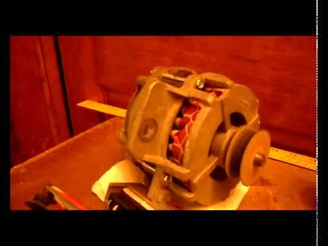
Also, In the photos it does not appear to be a BLDC. How do you know it is rated 500W? Please post pictures of motor, nameplate, and terminals or wires. Where did you get it?
biLeave a comment:
-
Gentlemen, you know that there are brushless motors with 3 wires, therefore three-phase, and those with direct current, naturally with 2 wires where the rotation of the stator magnetic fields is obtained by an electronic circuit that reads the position of the rotor through a sensor.Leave a comment:
-
In memory of John Bedini motor generator lee matrix been experimenting for decades.


Leave a comment:
-
About the REGENX
Let me point out why Thane is not being excepted as legit. Take a look at this statement from the Ottawa science community..........
" Complicating the analysis of Heins’ apparatus is the fact that he is not running his motor at full voltage and normal speed. Instead, he supplies it from a variac (a device for varying AC voltage), at a voltage well below the 120V that the motor is designed for. As a consequence, it runs at only a few hundred revolutions per minute, instead of the approximately 3500rpm"
And most people see this and think Thane is a huckster. Induction motor run full speed at 50vac all the way to 120vac. See how easy it is to trick you? Thane's discovery will make all of the other story book experiments look like toys. This is why Thane is rejected.
Rejecting an honest demo of Thane's work shows intent. Instead he is portrayed as a fraud. Here is the website of clown engineers who have no clue.
http://www.ottawaskeptics.org/2008/0...hermodynamics/
here is one more foolhardy slander
" Running it at such a low speed causes it to overheat,"
False, induction motors do not run below their rated rpm until they are severely overloaded. Thane is running his grinder motor at 150watts on up to 280watts for a 1/2hp. Clearly the people who are afraid of Thane don't do any bench work. Most go with this line of reasoning going along just to get along. The blind following the blind is so much like the masses it's laughable.
My 1/2hp washing machine motors top out at 9amps and that is the run load draw right on the nameplate or sticker.
A new day is dawning and the worry warts are going to be dumbstruck.
Here is Ottawa's final assessment of poor ole despised Thane based on their infinite reasoning powers that most of you agree with.
"Conclusion
Heins appears earnest and basically honest, but persistently self-deluded."
 Last edited by BroMikey; 05-28-2022, 07:09 PM.
Leave a comment:
-
That thing is banging. OMG and losing or wasting power from all the friction. Cadman is right a slipping the pulley for start up. Regardless of the name plate of the motor you are calling your motor, brushless, and yet it runs straight off the battery. That don't make sense.
A brushless dc motor has 3 wires or 3 phases and a sensor. You have 2 wires so it is not a conventional brushless motor.
It strikes me as a starter motor and you removed the rotor winding and brushes. When you removed the rotor windings was it like the alternator winding? This will help us to determine what motor you have without a name plate.
If it runs already on 24vdc off a battery you can pulse it with almost any high efficiency scooter pwm but that won't make it OU. You might gain 10%. What you are looking for is the magic of entropy with a weighted flywheel gaining momentum from earths rotational energy.
There is a place you can get where you collect extra inertia. My best understanding is that you get the weighted wheel moving and it takes 1X input but then upon taking energy out you get 3X or 2X output. Is this what your device is trying to do?
If you are trying to build a flywheel motor / generator that puts out more than it takes to run it let me know.Last edited by BroMikey; 05-28-2022, 06:12 PM.Leave a comment:
-
VID-20220528-WA0001.mp4.zip Cadman,
I know that I have a lot of mass and therefore a lot of inertia at the start, but being the motor from 500w to 24v, and having calibrated the pulleys in a suitable way, it has no difficulty in picking up the motor speed, also because in the initial part of the start the alternator is disconnected and therefore the effort is minimal, within the reach of that motor (which for skeptics is a 24v - 500watt- brushless) Instead of carbon brushes I have now used a thin copper rubbing plate which seems to go better. The problem is that now, since it was a motor not for continuous duty, but max 5 minutes, during the various tests it overheated and now it no longer shows signs of life, it must probably be the electronic circuit that controls the reversal of the magnetic field. of the brushless, I will try to repair it otherwise I will take another one, but this time for continuous service.
IMG-20220528-WA0000.jpgLeave a comment:
-
Memphis,
Look at the design of your device. You have a lot of mass that you are trying to accelerate from a dead stop to the full motor rpm. The startup power requirements are too high and your motor does not have enough power to do that quickly, so no electrical circuit is going to fix that.
The belt and pulley system you have is a power robber. The belts themselves absorb power just from flexing and the shaft bearing side load it takes for those belts to engage the pulleys is high.
You should to reduce those loads as much as you can (chains and sprockets or toothed belts and pulleys or ?) and use some type of clutch so you can bring your motor up to speed quickly and then slowly apply power to the rotating assembly to get it up to speed.
A loose motor belt with a tension pulley you can manually engage might do the job, and a small flywheel attached at the motor shaft might help.
Cadman
edit: I assumed those are v-belts, it's hard to tell. Regardless, you need to get the motor up to speed and slowly apply power to the rotating assembly.
Last edited by Cadman; 05-28-2022, 01:29 PM.Leave a comment:
-
the motor is 500w, but it is a brushless, and I have seen that almost all the wpm controls are not suitable for brushless motors.Leave a comment:
-
50% duty cycleOriginally posted by Memphis View Post
Thx Gyula
https://www.amazon.com/Controller-Di...%2C126&sr=8-18
Why not buy this? We still don't know how many watts he needs. 500w or 2000w?
https://www.amazon.com/Controller-El...s%2C126&sr=8-6Last edited by BroMikey; 05-28-2022, 05:14 AM.Leave a comment:
-
Hi Bro,
You attached a schematic on a DC motor speed controller (Motor PWM) for the 555 timer IC in your post here:
http://www.energeticforum.com/forum/...204#post510204
Unfortunately, there is an error in the schematic: both 1N4148 diodes are shown with their anodes connected to Pin 7 of the 555. To get a correctly working PWM control, any one of these diodes should be flipped so that a diode cathode and and the other diode's anode be connected to Pin 7. It was not you who made the schematic I believe but it would be good to correct it.
Such drawing error can be found also in a LED dimmer circuit here but fortunately attention was drawn to it under the wrong schematic: https://forum.allaboutcircuits.com/t...nerator.93148/ see correct schematic for the LED dimmer here: http://www.555-timer-circuits.com/fo...r.65/#post-406
See another correct drawing for instance to control duty cycle and the pulse frequency independently from each other here: https://www.electroschematics.com/pu...ator-with-555/
Of course, the pulse output Pin 3 of the 555 should go to the device to be controlled i.e. to a LED or to the base of the motor driver transistor.
GyulaLast edited by gyula; 05-27-2022, 02:41 PM.Leave a comment:
-
IMG-20220526-WA0005[1].jpg IMG-20220526-WA0006[1].jpg IMG-20220526-WA0007[1].jpg to try to explain myself better, why a speed regulator for brushless motors is not good for me, I need to send the current in full pulses, but of adjustable duration, so I tried to put a brush on the flywheel shaft which I connected to the negative of the motor, and I obtained a copper contact that engages about half of the circumference of the shaft, so half a turn the motor has current, and the other half a turn does not. In this way the system starts up as soon as the brush comes into contact with the copper part. The problem that as soon as it starts to turn, takes a minute and the brush burns the copper wire to which it is connected, I have already burned 3, you have to look for another solution, so I was looking for an impulse circuit (so I also avoided the large sparkle of the brush as the current passes) I am putting the photos to you to make you understand.Leave a comment:


Leave a comment: