Announcement

Collapse
No announcement yet.

Motor Generators

Collapse
X
 
  • Filter
  • Time
  • Show
Clear All
new posts

  • BroMikey
    replied
    Hi Memphis
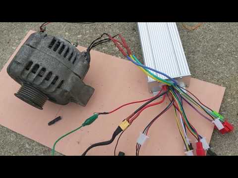
    Looks like it is a 24vdc golf cart motor so it is like a universal motor some call "series wound" especially since you had to remove brushes and add magnets so everything I said about universal motors apply. By removing the commutator action with it's windings in series with the outside windings you have eliminated the timing for which the motor coils fire. Therefore you will need a circuit that fires pulses based on a sensor you will need to place on the shaft.

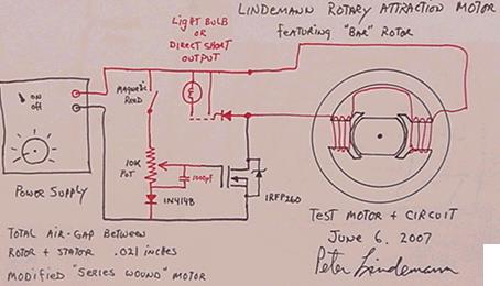
    Did you see my earlier post of Peter Lindemann's simple / effective circuit for a universal motor? His little circuit does the pulsing using a magnetic reed switch plus recovers all of the collapsing field energy back to an extra battery. You could use a hall effects switch also.

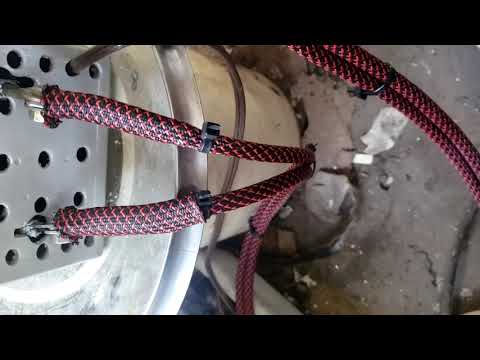
    Here it is and how when taking out the rotor you hook the 2 outside windings
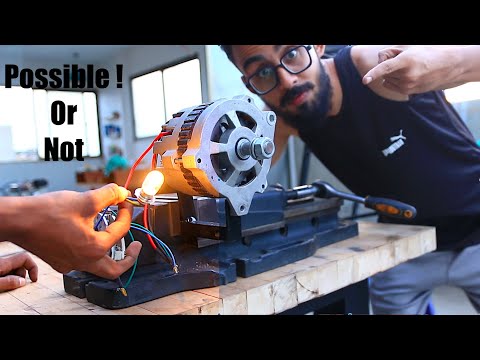
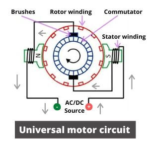
    Last edited by BroMikey; 05-20-2022, 05:16 PM.

    Leave a comment:


  • Memphis
    replied
    Mikey what you see disassembled is the three-phase 24v alternator of a bulldozer to which I replaced the rotor winding with magnets (so I also eliminated the brushes and the control circuit, now the output varies according to the speed of rotation, at 2500 rpm it takes out 42V.) The motor is the black one you see mounted in the photos on the right, it is a 24V, 500watt direct current.Now I need to power that pulse engine.Thanks always for the help.

    Leave a comment:


  • BroMikey
    replied
    Here is one with magnets modified rotor and controller same as your 3 phase motor same as a 3 phase alternator with the rectifier removed. Everybody is doing this, this is nothing new. It works well from what I hear. You do not have a universal motor, you had a 3 phase motor that you have converted to a 3 phase DC brushless PMM ( PMM = permanent magnet motor) this is a winner.

    If your motor is 220v you might be in trouble finding a controller for high voltage. I have seen up to 90vdc.

    Notation: disregard all entries about universal motor controllers.

    Last edited by BroMikey; 05-20-2022, 05:55 AM.

    Leave a comment:


  • BroMikey
    replied
    Watch him, he shows you what buy and how to wire it up with a common brushless controller off of Ebay or Amazon.

    Leave a comment:


  • BroMikey
    replied
    If this is your motor then it is a 3 phase motor. You can easily buy off the shelf ESC controller to run this motor. It is identical to a car alternator with the exception that there is no bridge rectifier.

    Last edited by BroMikey; 05-20-2022, 05:18 AM.

    Leave a comment:


  • BroMikey
    replied
    Memphis

    This is what you are doing except the outside winding in your case is not 3 phase so you can't use the RC out of the box ESC controllers that have built in timing.

    Look on your motor plate for RPM, if it is 3600 the motor is two pole or 2 phase. You are creating a BRUSHLESS DC motor and your rotor windings are just like an alternator rotor.

    Do you know if the motor plate says 1ph or single phase? Or is your motor a 3 phase motor?

    Last edited by BroMikey; 05-20-2022, 04:57 AM.

    Leave a comment:


  • BroMikey
    replied
    This universal motor dia is better because it shows all of the windings and how they are connected. When you chop off half the windings the resistance is less and 115v will melt the remaining winding. I want to do this myself and have been thinking about it.

    Come to think about it start at 20v and go higher till the amp draw rating peaks.

    You will need more than a pulse circuit you will also need the circuit to use a hall effects sensor to time the pulses. Normally the timing is done by way of the commutator.

    Last edited by BroMikey; 05-20-2022, 04:21 AM.

    Leave a comment:


  • BroMikey
    replied
    Also Memphis
    You will be interested to know that Peter Lindemann gutted a universal motor rotor but he did not use magnets, he use a solid rotor and he got good results. Without magnet just a piece of iron for the rotor he got good power and more RPM's than when the motor was made using only 20vdc pulsed. This is because the universal has 2 windings and they are the rotor winding plus the outside winding in series. I repeat both windings are in series running on 115vac or 115vdc. BUT when you remove half the windings you will not be able to run the outer winding on 115v because of the amp draw. You must find the right voltage for your converted motor by slowly increasing the volts while measuring the amps in your winding being careful not to exceed the awg wire rating. You can look at the motor plate and see the rated amps. When the amps are reached that will be your max voltage.

    This is a general dia of a universal motor but the rotor winding are not shown.

    Last edited by BroMikey; 05-20-2022, 04:02 AM.

    Leave a comment:


  • BroMikey
    replied
    Thanks Memphis

    I am straight up now. You have a motor where the rotor has a winding on it normally but you eliminated the brushes and the winding which creates a magnetic field was replaced with magnets. Your motor is called a "UNIVERSAL MOTOR"

    This is not an easy task, look at a treadmill circuit board / controller they are using a universal motor or a PMM. You can power a universal motor with AC or DC. They are the same as a drill motor which can run on either. I am unsure what the inspection plate says on your motor.

    You are somewhere in between but now a PMM, try 48vdc and work your way up with a Variac is a good first step. Because you took out half the windings.

    Ask David Bowling, he is powering a universal motor up and changing the RPM's
    He could tell you where to buy one. How about it Dave, got any inklings?
    .................
    Last edited by BroMikey; 05-20-2022, 03:43 AM.

    Leave a comment:


  • Memphis
    replied
    IMG-20220519-WA0005.jpg this is the machine, of course being a test I didn't waste too much time to look after the appearance and I used recycled materials, so don't pay attention if the structure seems a bit strange, the important thing is that it absolves me well task. Now I would need a scheme for powering the engine at short adjustable periods to find the best combination to give the flywheel enough momentum and keep the batteries charged. IMG-20220519-WA0006.jpg

    Leave a comment:


  • Memphis
    replied
    IMG-20220519-WA0009.jpg IMG-20220519-WA0012 (1).jpg IMG-20220519-WA0011.jpg IMG-20220519-WA0010.jpg no, I don't convert an alternator into a motor, I just modified the motor to avoid it using a part of current to produce the magnetic field of the rotor, now I will try to post the photos.this is the rotor I modified
    Attached Files

    Leave a comment:


  • BroMikey
    replied
    Hey Memphis
    I understand your request now. Everybody is converting an alternator to a motor. I like this conversion and see his part 1 video before this one. He uses off the shelf easy to get your hands on components. That's the way to go. Is this what you want?

    Leave a comment:


  • Memphis
    replied
    I will try to explain myself better in detail. I took a 24v alternator of a caterpillar, and I modified the rotor by inserting strong magnets to make it brushless, now according to the rotation speed the output in volts varies, which I will try to regulate on 24v to be able to charge the batteries . The motor is also a brushless, I have already tried to make them rotate at the same time without flywheel to see if they were self-sufficient, following an idea of those that run on youtube, of course yet another fake, the alternator cannot give enough current, so I thought of modifying it by adding a flywheel to take advantage of its inertia and give continuous thrust to the alternator while the engine works briefly to save energy and try to avoid the back-emf.

    Leave a comment:


  • BroMikey
    replied
    Here is an excellent example of low drive motor input driving a second rotor plus the free wheeling arm on the grinder. This is so far above the sceptic all they can do is eat Thane's dust.

    A single regenX generator coil far left, in the center section a regenX motor with readings displayed. How would one dismantle the drive section and for what purpose? 4 years ago.

    Everything here is nearly identical to John B. SG having a rotor with magnets and coils acting on the magnets to motor along and also collect back the collapsing field all at the incredibly slow speed of 300 rpm's. Then generator coils were also part of the same rotor but in Thane's video for the sake of demonstration lowering confusion a second rotor holds the generator coil (singular)

    The rpm is now over 10X faster where cop is higher that cop = 1 as with the SG. It's a motor generator folks and everyone knows who inspired the concept.

    Last edited by BroMikey; 05-19-2022, 05:38 AM.

    Leave a comment:


  • BroMikey
    replied
    Originally posted by Turion View Post

    bro,
    If Thane claiming his system is a self runner,..... How do we calculate that without knowing what it requires to run the motor UNLOADED? That's basic info.
    Exactly, that basic info of the unloaded condition has been part of all of Thane's video's for a decade. Why the site controllers reject Thane on that basis shows they do not see Thane's video's and the mere questioning of his personal integrity is enough to let Thane know he is unwelcome.

    What an extra grinder motor pulling a static wattage of 75watt will change whether or not Thane's motor generator is now viable? Thane is smart enough to know when he is being abased by many who spoke to soon.

    Thane does not need this site to get his work noticed but it sure would have been nice to see Lindemann and Dollard receiving Thane with open arms so he could be challenged in person. Dollard does not believe Thane has anything.

    The site controllers made a choice, so be it. With Aaron stuck in the middle trying to please all of those who spoke out against Thane early on. There must be something I don't know. Who would have been embarrassed? John gave the principles a green light but John is not here is he?

    Anyone who in interested may see the many years of Thane's presentations complete with unloaded drive motor readings displayed on his power analyzer, so to challenge Thane based on a lack of fundamental data sends a signal that he must be hiding something already shown. The message is "We don't see your video evidence nor believe you" but you know as well as I do the principles work the same on your incomplete setup.

    See you in a few weeks, I hope your visit is a good one with the family.

    PS here is my finished soldering / iron lead welder for the Alum battery posts

    Last edited by BroMikey; 05-19-2022, 04:15 AM.

    Leave a comment:

Working...
X