-
VID-20220528-WA0001.mp4.zip Cadman,
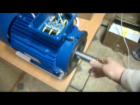
I know that I have a lot of mass and therefore a lot of inertia at the start, but being the motor from 500w to 24v, and having calibrated the pulleys in a suitable way, it has no difficulty in picking up the motor speed, also because in the initial part of the start the alternator is disconnected and therefore the effort is minimal, within the reach of that motor (which for skeptics is a 24v - 500watt- brushless) Instead of carbon brushes I have now used a thin copper rubbing plate which seems to go better. The problem is that now, since it was a motor not for continuous duty, but max 5 minutes, during the various tests it overheated and now it no longer shows signs of life, it must probably be the electronic circuit that controls the reversal of the magnetic field. of the brushless, I will try to repair it otherwise I will take another one, but this time for continuous service.
IMG-20220528-WA0000.jpgLeave a comment:
-
Memphis,
Look at the design of your device. You have a lot of mass that you are trying to accelerate from a dead stop to the full motor rpm. The startup power requirements are too high and your motor does not have enough power to do that quickly, so no electrical circuit is going to fix that.
The belt and pulley system you have is a power robber. The belts themselves absorb power just from flexing and the shaft bearing side load it takes for those belts to engage the pulleys is high.
You should to reduce those loads as much as you can (chains and sprockets or toothed belts and pulleys or ?) and use some type of clutch so you can bring your motor up to speed quickly and then slowly apply power to the rotating assembly to get it up to speed.
A loose motor belt with a tension pulley you can manually engage might do the job, and a small flywheel attached at the motor shaft might help.
Cadman
edit: I assumed those are v-belts, it's hard to tell. Regardless, you need to get the motor up to speed and slowly apply power to the rotating assembly.
Last edited by Cadman; 05-28-2022, 01:29 PM.Leave a comment:
-
the motor is 500w, but it is a brushless, and I have seen that almost all the wpm controls are not suitable for brushless motors.Leave a comment:
-
50% duty cycleOriginally posted by Memphis View Post
Thx Gyula
https://www.amazon.com/Controller-Di...%2C126&sr=8-18
Why not buy this? We still don't know how many watts he needs. 500w or 2000w?
https://www.amazon.com/Controller-El...s%2C126&sr=8-6Last edited by BroMikey; 05-28-2022, 05:14 AM.Leave a comment:
-
Hi Bro,
You attached a schematic on a DC motor speed controller (Motor PWM) for the 555 timer IC in your post here:
http://www.energeticforum.com/forum/...204#post510204
Unfortunately, there is an error in the schematic: both 1N4148 diodes are shown with their anodes connected to Pin 7 of the 555. To get a correctly working PWM control, any one of these diodes should be flipped so that a diode cathode and and the other diode's anode be connected to Pin 7. It was not you who made the schematic I believe but it would be good to correct it.
Such drawing error can be found also in a LED dimmer circuit here but fortunately attention was drawn to it under the wrong schematic: https://forum.allaboutcircuits.com/t...nerator.93148/ see correct schematic for the LED dimmer here: http://www.555-timer-circuits.com/fo...r.65/#post-406
See another correct drawing for instance to control duty cycle and the pulse frequency independently from each other here: https://www.electroschematics.com/pu...ator-with-555/
Of course, the pulse output Pin 3 of the 555 should go to the device to be controlled i.e. to a LED or to the base of the motor driver transistor.
GyulaLast edited by gyula; 05-27-2022, 02:41 PM.Leave a comment:
-
IMG-20220526-WA0005[1].jpg IMG-20220526-WA0006[1].jpg IMG-20220526-WA0007[1].jpg to try to explain myself better, why a speed regulator for brushless motors is not good for me, I need to send the current in full pulses, but of adjustable duration, so I tried to put a brush on the flywheel shaft which I connected to the negative of the motor, and I obtained a copper contact that engages about half of the circumference of the shaft, so half a turn the motor has current, and the other half a turn does not. In this way the system starts up as soon as the brush comes into contact with the copper part. The problem that as soon as it starts to turn, takes a minute and the brush burns the copper wire to which it is connected, I have already burned 3, you have to look for another solution, so I was looking for an impulse circuit (so I also avoided the large sparkle of the brush as the current passes) I am putting the photos to you to make you understand.Leave a comment:
-
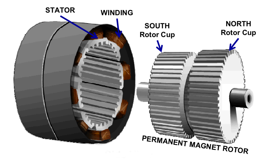
This guy's company uses regular 3 phase cages. Here is what they do
A permanent magnet generator 5,5 kW 1500 rpm 220V It can be used for hydroelectric power. On small speeds, as in video, it produces up to 50 V. The grid tie inverter generates up to 120W. Our company produces generators with power from 500 W to 30 kW, speed 100 to 3000 rpm
sales@windkraft.com.ua
Totally cogging free, well almost, we know better. Much better than the old way till she starts pullin a large load. It's a little better. You can order the rpm best for your project. Still way under unity.
Leave a comment:
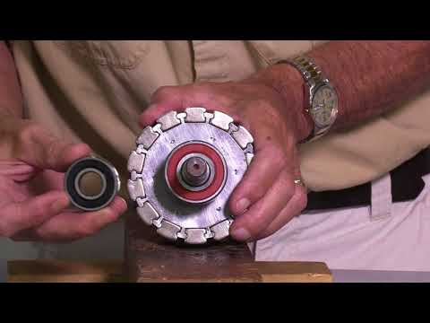
-
This is how Jeff's rotor looks. The bearings are bigger and the whole thing operates at a lower speed. If you put one on a car for instance, you wouldn't need a 3 or 4 to 1 ratio like a Delco running at 6,000-8,000 rpm's. This one could do well at 1500 rpm's. This is much lower.
 Last edited by BroMikey; 05-25-2022, 02:57 AM.
Leave a comment:
-
Dear Memphis and to the entire group.
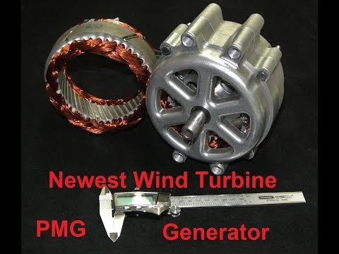
I will say it again as I have so many different ways, the people showing excess energy from their motor generator schemes have modified the generator to low cogging. If you don't know Jeff at Missouri Wind and Solar I'll tell you he has been around for years developing a low cogging alternator.
The early video shows the original stator core and the updated video also of Jeff shows you how he won the battle. He has no problem sharing it because no one else can make the changes.
This new design has a greater efficiency. Low cogging stepper motors used this same approach.

Last edited by BroMikey; 05-24-2022, 05:32 AM.Leave a comment:
-
I have had one of those 555 timer books from radio shack since the early 70's and I always fall back on it. Great way to start, some of the best circuits are in there plus all of the parts are listed.Originally posted by Turion View Post http://vtda.org/books/Electronics/IC...alterGJung.pdf
https://ibiblio.org/kuphaldt/socratic/model/mod_555.pdf
This one is real easy
https://www.n5dux.com/ham/files/pdf/...20Circuits.pdf
.........................Last edited by BroMikey; 05-23-2022, 06:14 AM.Leave a comment:


Leave a comment: