-
I call it open loop because it does not lock the flux into one place(pole) instead is given an alternative route. Let's call it a "closed path" between cores.Originally posted by Turion View Post
John Bedini taught us about closed and open systems. He showed us how circuits that are electrical, need not dead end and burn up. Same with flux, it does not have to stop/lock things up, given a choice will take the least resistance traveling back around to the other side.
Going all of the way back to the opposite pole takes time.
 Last edited by BroMikey; 02-23-2022, 05:37 PM.
Leave a comment:
-
Okay thanks, I missed those guys saying any of that. I had to think it thru for myself. Often people who teach do not make these messages clear and the years roll by. Also I don't trust much of what I hear and only half of what I seeOriginally posted by Turion View Post
Last edited by BroMikey; 02-23-2022, 05:44 AM.Leave a comment:
-
The strap on the coils and the “C” core are for the same reason. They help to keep a closed magnetic loop. Peter L. shows us with the rotary attraction motor this “closed magnetic loop” eliminates or reduces Lenz. So a GENERATOR built on the same principles will ALSO eliminate OR reduce Lenz as Mr. Angus Wangus demonstrated countless times. This is ANOTHER way of reducing or eliminating Lenz without worrying about wire length and core materials or RPM. Lenz free at ANY speed.
BUT, you still must neutralize the attraction of the rotor magnets to the core material when you have multiple coils. Or eliminate it in the first place and still get generated power in the core. The principles for how to do that MAY have been made public and shown here. I am doing some testing to find out before I open my mouth about it. You must remember that any principle shown for motor design MAY work in generator design. I have seen an interesting principle shown in a new kind of MOTOR design that I want to test in a new kind of generator design. We will see what happens.
Leave a comment:
-
My main man. Great adventure ahead. I would be interested to see a coil pack with say 96v @ 3 amps under load, no heat troubles. I think coils on opposite sides helps the process this is why Thane (in early models like yours) would put a strap of iron clear from one side on the back of a core to the other side for testing and after that "C" cores were born.
Having a C-Core N and S creates an open loop for flux. Your double coil packs must do the same thing. Again just more brain farting, I have no proof of anything, only speculation.
This is a resistance and reactance change as well as giving the flux an alternative path. Like cooking everything changes the taste fast. You are cooking.Originally posted by Turion View Post Smoking hot. Think effort and faith mixed with perception. We know the energy is there
Last edited by BroMikey; 02-22-2022, 04:44 PM.
Smoking hot. Think effort and faith mixed with perception. We know the energy is there
Last edited by BroMikey; 02-22-2022, 04:44 PM.Leave a comment:
-
First thing I am going to do tomorrow is put in a second core of the new permalloy, since I have lots of those, and see what the combined voltage two coils is. If I recall, I got 96 volts out of a coil pair, yet I am only getting 33 volts out of a single coil. Then I will put in a coil pair of the iron coils and compare.
I will work on trying to get the longer core to fit in the hole. If I can do that, and the voltage goes up significantly, that is where I will start. If it does NOT, I will unwind a coil and replace the three strands of 1,000 feet with 12 strands at 250' each, and I can see how the combinations affect the coil performance at different speeds with the new core material. I have several spools that have 600-800 feet of #23 on them that I can cut into either 500 foot strands or 250 foot strands, since right at 3,000 ft of #23 is what fits on a spool.Leave a comment:
-
24 magnets @ 2800 RPM = 67200/60 = 1120HZ HF will bottle neck with the old coil design.
You must go back to your old multifilar coils and do combinations, there you will find a high voltage. The curve will top out and drop off. You must find it. You are the man who taught me this. Get on it. 2.4 amps is cool. Try a shorter wire, not longer. 600ft to 750ft should do it and you may have to settle for a lower volts but real high amps using HF
Try parallel series combinations, you know the drill homie. To bad you lost your 12 filar coil.
PS just got in from the 6th day of chemo this month's cycle. 1 more to go.Last edited by BroMikey; 02-22-2022, 02:24 AM.Leave a comment:
-
The Permalloy doesn't assist through faster inductive collapse. The iron core holds enough flux to dissipate over time.Leave a comment:
-
Not so great news on the generator front today. I tested 3 coils. The original iron core. The new permalloy core. The extended permalloy core. I am pretty sure the new permalloy core did NOT go all the way in, so I have some grinding to do on it to see if I can get it to go another 1/4" into the coil holder. Anyway, these were the results with a 100 watt bulb as load on a single coil.
Iron core 35 volts @ .4 amps
Permalloy coil 33 volts at .4 amps
Extended permalloy core with an additional 900 feet of wire. 14 volts @ .25 amps. SORRY! 2.5 was a typo!
I am not understanding why the old rotor with only 12 magnets produced higher voltage on the old iron cores of over 120-130 volts across the 300 watt load, and at a higher amperage. (The amperage is understandable, since the load was bigger)
I am going to put the 300 watt bulb in and run everything the same to see if the amps will go up with a bigger load. And I will keep working on getting that coil to go in farther. Tomorrow is another day.
I shot videos of all three of my tests, but with such disappointing results, I saw no need to post them.
EDITED TO CORRECT ERRORLast edited by Turion; 02-22-2022, 04:09 AM.Leave a comment:
-
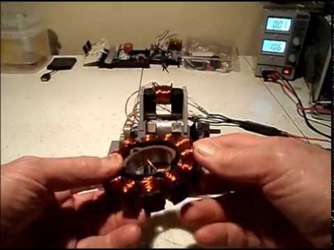
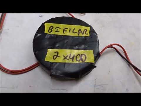
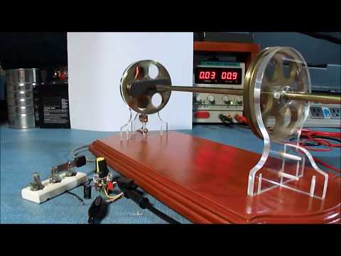
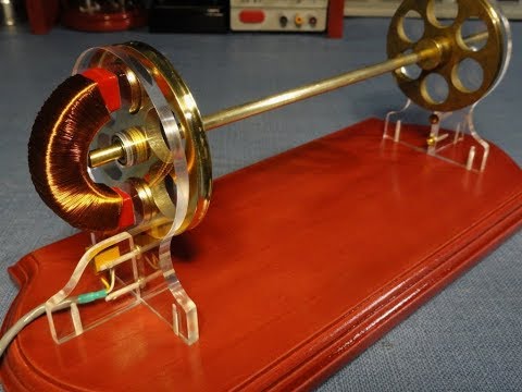
Nicola Tesla said in 1894 that bifilar coils could reduce a certain self-inductance which arises in copper wire coils, when they generate electricity. This self-inductance (or magnetic self-repulsion) makes the generating process inefficient, especially at high voltages and high r.p.m. (see the patent US512340A or https://teslauniverse.com/nikola-tesl... or https://patents.google.com/patent/US5...). In order to test his conclusions again now in 2020, we made a series of suitable wire coils with 800 turns of 0.50 mm PEI-coated copper wire (and many other coils not shown in this video). They were wrapped by hand as “monofilar”, “bifilar”, “quadrifilar untwisted” or “quadrifilar twisted” (into a helical shape), and also “monofilar with an iron centre”. We tested these various wire wrappings both around central formers made of wood or iron, and also as pancake coils with wire running fully into their centres. Our results confirm that any wire coils with significant capacitance (the easiest to make of which is “bifilar”) give 50% higher output currents at 500 r.p.m. in a standard test system (using 12 N-S-N-S neodymium magnets spinning above a single coil on a rotor), than for standard monofilar coils which have hardly any capacitance. We placed all of our test coils over 3-mm-thick, mild-steel discs to help extend the rotor magnetic field across their heights, while we did not place iron inside of any of our coils, except in one control example, because it impairs free spin of the permanent-magnet rotor due to para-magnetism. Many thanks to K.B. and A.M. for their skilled help!Originally posted by Turion View Post
 Last edited by BroMikey; 02-21-2022, 06:54 AM.
Leave a comment:
-
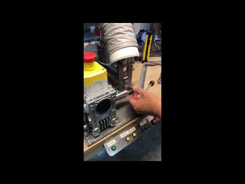
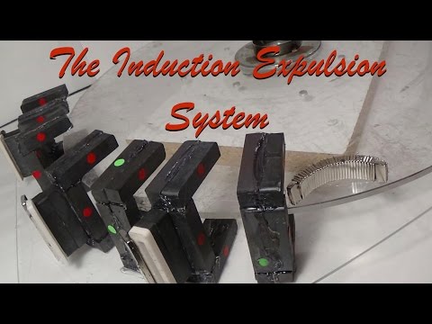
This is something else, it is another "C" Core motor which has both North and South firing at the same time. This lowers magnetic "LOCK" he has a patent number
Leave a comment:
Leave a comment: