Originally posted by Matthew Jones
View Post
HI Matt glad you are back with earth shattering revelations about a bowel movement.
 isn't he a genius?
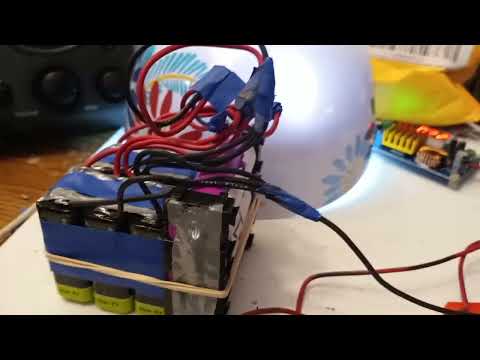
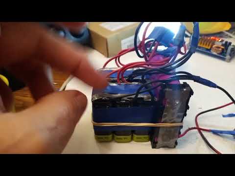
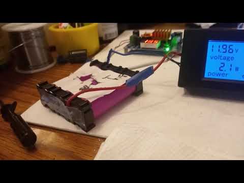
Anyway back to the slam. Ending pack voltage 1st run charge up picture and 2nd run start up voltage.


.............................................


Leave a comment: