Announcement

Collapse
No announcement yet.

My Motors got me to Tap into Radiant Energy

Collapse
X
 
  • Filter
  • Time
  • Show
Clear All
new posts

  • iankoglin
    replied
    Originally posted by JohnStone View Post

    BTW: I will continue motor building . Is it still advisable to use a 20 pole armture with 4 brushes / magnets?
    I have now two identical motors 36V 1000W.
    I will cut housings at shaft side in order to get magnets of both housings together like magnets of double length. Then I will put both armatures on one new long shaft. Commutators and brushes will sit at both ends at their genuine place like before.

    Armatures are somewhat shorter than magnets. Is that a drawback? I would like to prevent cutting magnets.

    JS
    G'day John
    My Monster 5.1's work great thanks for your designing of them
    My 1000w motor has larger bearings on the shaft side and my motors have the same longer magnets. I am getting my engineering friend to make a new shaft that is the same size to fit the bearings on the commutator end and continue or rather extend the shaft at both ends so I can use either end to drive the tricycle it will be used in at the moment the thread is ccw I will have cw one end and ccw the other. The wiring of the armature is .8mm diam. I have some wire but it has/is used in other coils and they were litzed and therefore if I stretch them to make then straight they will be thinner so I ordered .8mm from off EBay it is coming from the US I imagine I will have it within the next week or two by then I will have the motor Mods finished.

    One Question my friend about your monsters Please can I use them in place of the Mosfets in the "Happy Motor Circuit" I did try them 3 times with an Oscillator I purchased on EBay but they the Oscillators became defunct.
    Please I would like your opinion regarding this when you have time

    Kindest Regards


    Kogs still working at it

    Leave a comment:


  • Ufopolitics
    replied
    Is Fine John...

    Originally posted by JohnStone View Post
    Ufo, yes well I will do it. You intend to add a cap at coil and at armature turning along coils.
    But any simulations will not take care of HER. She is completely tranparent for any human made simulation.
    Anyway I expect no sudden pulses or current interruption like before but oscillations of that tank circuit. Special case if we hit resonance with pulsing frequency or on/off from commutator segements or both.

    BTW: I will continue motor building . Is it still advisable to use a 20 pole armture with 4 brushes / magnets?
    I have now two identical motors 36V 1000W.
    I will cut housings at shaft side in order to get magnets of both housings together like magnets of double length. Then I will put both armatures on one new long shaft. Commutators and brushes will sit at both ends at their genuine place like before.

    Armatures are somewhat shorter than magnets. Is that a drawback? I would like to prevent cutting magnets.

    JS

    Hello John,


    I know "simulations" are written by Humans... ...and they do not include/accept HER (so far..)...but I was referring to Hot Side behavior.

    On Your build, that is a great Motor!, a P20 is same as my BADSEY/BOSCH Motor...Very strong!

    It does not matter that Armature lamination area, is smaller than magnets...what should not be is the opposite. Think that you will be designing the size/strength of your rotor magnetic fields...so, you could expand them or shrink it to size...

    On My BOSCH I used 18 gauge...and 21-22 turns per Coil...a P21.

    But later on, after I have already built it...I came up with the Quad Pentagons Design...However, I have not build that type yet...


    Warm Regards


    Ufopolitics

    Leave a comment:


  • JohnStone
    replied
    Originally posted by Ufopolitics View Post
    ... John, could You, please, simulate also an LC (Capacitor and Coil) in parallel, individual connections?...using same parameters/comparisons as you have shown above? ....
    Ufo, yes well I will do it. You intend to add a cap at coil and at armature turning along coils.
    But any simulations will not take care of HER. She is completely tranparent for any human made simulation.
    Anyway I expect no sudden pulses or current interruption like before but oscillations of that tank circuit. Special case if we hit resonance with pulsing frequency or on/off from commutator segements or both.

    BTW: I will continue motor building . Is it still advisable to use a 20 pole armture with 4 brushes / magnets?
    I have now two identical motors 36V 1000W.
    I will cut housings at shaft side in order to get magnets of both housings together like magnets of double length. Then I will put both armatures on one new long shaft. Commutators and brushes will sit at both ends at their genuine place like before.

    Armatures are somewhat shorter than magnets. Is that a drawback? I would like to prevent cutting magnets.

    JS
    Last edited by JohnStone; 08-03-2013, 08:47 PM.

    Leave a comment:


  • Ufopolitics
    replied
    Excellent Analysis!

    Originally posted by JohnStone View Post
    Advantage of pulsing:
    This night I continued simulating pulses on a coil. Same coil 100mH and 5 Ohm resistor.
    Voltages: 12, 24, 36,48,60
    Period: 22 ms
    Variation: Adjusting duty cycle as to result in very same resistor loss.

    Discussion:
    Pulse width needs to be decreased on a nonlinear way while coil energy stored increases linearly with voltage. Not amazing because curent increases linearly.
    Amazing is: with higher voltage and shorter pulses we get more energy into the coil, while losses in resistor are stable!!!!!
    Good news: pump more power in short time into your coils while not increasing losses! Harvest HER gift while extended off time.

    Please note: Symmetric motors do not make use of radiant and hence are not interested in harvesting after switch off. They require constant current flow into the motor.
    Here we are interested in pumping power into the coil in short time in order to make use of the magic ocurring after switch off.
    But of course we still need to put torque on the armature. Therefore we expect a sweetspot for torque and harvesting. And this sweet spot will be individual for every motor. load condition and speed. And please do not expecrt linear behaviour - a challenge for any controller!!

    BTW: I simulated for rectified mains as well pertaining constant loss. Pulse time decreases (compared to 12V) to 20% for 115V and 10% for 230V.
    This info is just for information. But please do not do that yourself. It is dagerous and might be lethal for you or others.
    JS
    Hello My Friend Sir John Stone!


    Excellent Analysis!...awesome...

    John, could You, please, simulate also an LC (Capacitor and Coil) in parallel, individual connections?...using same parameters/comparisons as you have shown above?

    Say we try to add "static" capacitance values (Cap Farads) within a closed range related to Coil Capacitance/Resistance...or above...

    We should figure Non Polarized Caps...since SHE will come in "reversed mode" ...even though I do not think both energies within one "ordinary" Container...will ever "add up"...since they are different energies nature...but we still could use advantages of both individually, even if they "do not mix"...similar as they both "live" within a Coil...

    It would be a nice Simulation to see...


    Kind Regards


    Ufopolitics

    Leave a comment:


  • Lightworker1
    replied
    Originally posted by JohnStone View Post
    @ALL: Please understand I designed this board for hand wiring - for everybody all over the world. I was not aware at that time that it will be multiplied as true PCB. We can enhance it for two layer PCB later on. And then we will add screw terminals, current sensor ...... and make it somewhat smaller.
    JS

    Hello John stone. Many thanks. I am really looking forward to the possible monster driver pcbs. At present, I am in the planning stage for the 4ch monster pulser. So in a way, I have some time at hand as I am currently trying all kinds of measurements on the dual pentagon motor.

    Good Luck.

    Warmest regards

    Nameste

    light

    Leave a comment:


  • Lightworker1
    replied
    Originally posted by JohnStone View Post
    Advantage of pulsing:
    This night I continued simulating pulses on a coil. Same coil 100mH and 5 Ohm resistor.
    Voltages: 12, 24, 36,48,60
    Period: 22 ms
    Variation: Adjusting duty cycle as to result in very same resistor loss.

    Discussion:
    Pulse width needs to be decreased on a nonlinear way while coil energy stored increases linearly with voltage. Not amazing because curent increases linearly.
    Amazing is: with higher voltage and shorter pulses we get more energy into the coil, while losses in resistor are stable!!!!!
    Good news: pump more power in short time into your coils while not increasing losses! Harvest HER gift while extended off time.

    Please note: Symmetric motors do not make use of radiant and hence are not interested in harvesting after switch off. They require constant current flow into the motor.
    Here we are interested in pumping power into the coil in short time in order to make use of the magic ocurring after switch off.
    But of course we still need to put torque on the armature. Therefore we expect a sweetspot for torque and harvesting. And this sweet spot will be individual for every motor. load condition and speed. And please do not expecrt linear behaviour - a challenge for any controller!!

    BTW: I simulated for rectified mains as well pertaining constant loss. Pulse time decreases (compared to 12V) to 20% for 115V and 10% for 230V.
    This info is just for information. But please do not do that yourself. It is dagerous and might be lethal for you or others.
    JS
    Hello John Stone. Many thanks for this insight.

    Warmest regards

    Nameste

    light

    Leave a comment:


  • Cornboy 555
    replied
    Next.

    Originally posted by JohnStone View Post
    @ALL: Please understand I designed this board for hand wiring - for everybody all over the world. I was not aware at that time that it will be multiplied as true PCB. We can enhance it for two layer PCB later on. And then we will add screw terminals, current sensor ...... and make it somewhat smaller.
    JS

    Sounds great John, by then we will probably need to put other bits on as well, Who Knows, i look forward to the future,

    Thanks Friend, Cornboy.

    Leave a comment:


  • JohnStone
    replied
    Originally posted by Cornboy 555 View Post
    Hey Kogs, thanks for the link, for some reason i was looking for screw terminal blocks, but 2.54 pitch are hard to find at any decent price.

    I am sure Sampojo will update price and availability of boards, when he sees these posts.

    He's the man on the ground, so to speak. @ Lightworker as well.
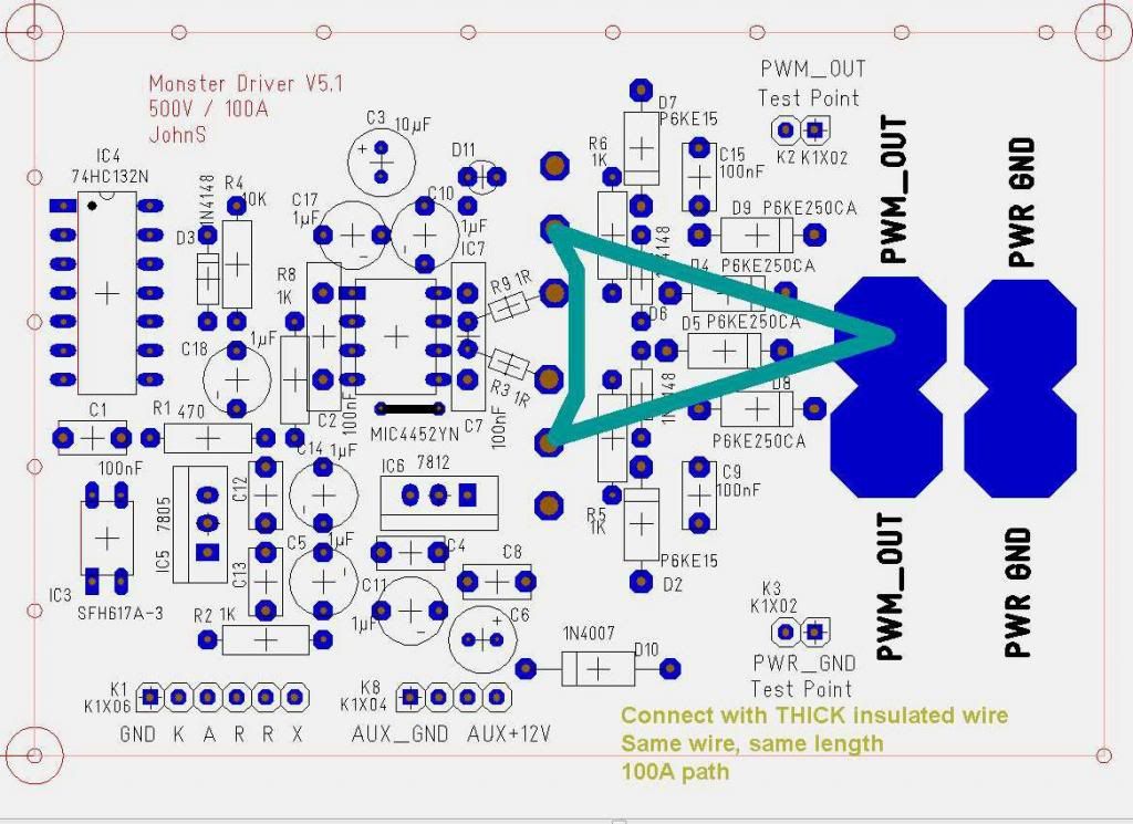
    @ALL: Please understand I designed this board for hand wiring - for everybody all over the world. I was not aware at that time that it will be multiplied as true PCB. We can enhance it for two layer PCB later on. And then we will add screw terminals, current sensor ...... and make it somewhat smaller.
    JS

    Leave a comment:


  • JohnStone
    replied
    Advantage of pulsing:
    This night I continued simulating pulses on a coil. Same coil 100mH and 5 Ohm resistor.
    Voltages: 12, 24, 36,48,60
    Period: 22 ms
    Variation: Adjusting duty cycle as to result in very same resistor loss.

    Discussion:
    Pulse width needs to be decreased on a nonlinear way while coil energy stored increases linearly with voltage. Not amazing because curent increases linearly.
    Amazing is: with higher voltage and shorter pulses we get more energy into the coil, while losses in resistor are stable!!!!!
    Good news: pump more power in short time into your coils while not increasing losses! Harvest HER gift while extended off time.

    Please note: Symmetric motors do not make use of radiant and hence are not interested in harvesting after switch off. They require constant current flow into the motor.
    Here we are interested in pumping power into the coil in short time in order to make use of the magic ocurring after switch off.
    But of course we still need to put torque on the armature. Therefore we expect a sweetspot for torque and harvesting. And this sweet spot will be individual for every motor. load condition and speed. And please do not expecrt linear behaviour - a challenge for any controller!!

    BTW: I simulated for rectified mains as well pertaining constant loss. Pulse time decreases (compared to 12V) to 20% for 115V and 10% for 230V.
    This info is just for information. But please do not do that yourself. It is dagerous and might be lethal for you or others.
    JS

    Leave a comment:


  • Cornboy 555
    replied
    Joe.

    Originally posted by iankoglin View Post
    G'day Cornboy
    Try here

    Buy PCB Headers 6W,1ROW STRT HEADER,GOLD TE Connectivity 826629-6 online from RS for next day delivery.

    Please how much are the Monster Boards?

    Kindest Regards

    Hey Kogs, thanks for the link, for some reason i was looking for screw terminal blocks, but 2.54 pitch are hard to find at any decent price.

    I am sure Sampojo will update price and availability of boards, when he sees these posts.

    He's the man on the ground, so to speak. @ Lightworker as well.

    Leave a comment:


  • Lightworker1
    replied
    Originally posted by Cornboy 555 View Post
    Hello everyone, just a couple of pics of John Stone Pulser boards that Sampojo, organised.

    Thanks Joe.

    [IMG][/IMG]

    [IMG][/IMG]

    Regards Cornboy.
    Hello Cornboy indeed these pcbs are beauty
    Looking forward to buying them.

    Warmest regards all

    nameste

    light

    Leave a comment:


  • Lightworker1
    replied
    Cornboy, You saw the email, we should have ours from OSHPark around July 12. I ordere

    Originally posted by sampojo View Post
    Cornboy, You saw the email, we should have ours from OSHPark around July 12. I ordered 20. we are getting ~$11/bd unit cost. I will have my hands full just assembling 4 and a spare or 2 and could part with the overage. I said what the heck, I wanted 5 or 6, and for around $100 on my own or teaming up with Cornboy, I got 4+ more. Ordered FETs, still trying to put together a BOM at Mouser for the rest. Just get a packet with everything in it... thats the plan.

    So Machine, Let me know if you are interested in these PCBs. (driver circuitry and FETs on same board). OSHPark planning to put them on his store. He will make a few and try to stay ahead of ordering rates. If he gets volume he may put it on his higher output line, may lower the end unit cost. I will try to get when he might post the PWM board.
    Hello Sampojo, looks like you have the info about the availability of these JS monster PCBs. Due to circumstances I got behind with this particular thread. Sorry about that. I am trying to go through various posts

    Many Thanks

    Warmest regards all

    Nameste

    light

    Leave a comment:


  • Lightworker1
    replied
    You can upload your design as an Eagle board file, or a ZIP file containing Gerber CA

    [QUOTE=iankoglin;235077]
    Originally posted by sampojo View Post
    HI John Stone, welcome back and hope your wife is doing well.

    I had been working on using ExpressPCB as a source of prototype boards until a member pointed out OSHPark, and I submitted your gerber files to them. ExpressPCB does not use gerber files from customers. So I had attempted to use their software to make a similar PCB to the T3001. I could not seem to crack design processes in T3001. I had been concerned about equidistance on the heavy leads and making the PCB separable between FETs and FET Drivers, As Don H and Dana seemed to like to build that board separated from the input section. You may have noticed some of those board designs I posted. Although OSHPark edges ExpressPCB out in price, its not by much and an alternate source may still be a good idea. So I hadn't posted the latest design to address the above concerns. So here it is.


    QUOTE]

    G'day Sanpojo and especially John Stone
    John Stone told me that R2 should be 330 ohms Not 1K ohms as shown
    Please confirm before Production
    Kindest Regards

    Kogs Just keeping his eye on things

    Many Thanks Kogs & @All posting this link about
    OSH Park PCB Order - Upload your design
    I am glad they are able to accept eagle cad files too.

    You can upload your design as an Eagle board file, or a ZIP file containing Gerber CAM files. See our design submission guidelines for more information.

    There is great wisdom in the following statement:
    Good teams make the most of individual and talents.
    UFOPOLITICS made This The Reality


    Planning my Monster Quad Pulser. One thing I do not want to reinvent if the Monster Pulser PCBs are already now available from PCB fab place.

    Warmest Regards All

    Nameste

    light

    Leave a comment:


  • iankoglin
    replied
    Originally posted by Cornboy 555 View Post
    The only part i am having trouble obtaining is the K1X02 04 06 terminal blocks, can you or anyone else sugest a supplier?


    Warm Regards To you and Your Family, Cornboy.
    G'day Cornboy
    Try here

    Buy PCB Headers 6W,1ROW STRT HEADER,GOLD TE Connectivity 826629-6 online from RS for next day delivery.

    Please how much are the Monster Boards?

    Kindest Regards

    Leave a comment:


  • Cornboy 555
    replied
    Black Beauty Indeed.

    Originally posted by JohnStone View Post
    @Cornboy: Wow. Black Beauty coming to life.

    I'd like to give you remote assistance at building process for your pulsers. We will do it here publicly in order to give others a tutorial as well.
    Give me some days in order to elaborate steps and advice.
    It is very helpful you own an ocilloscope and generator. You should own a solder pump for board repair.

    Outlok to the procedure:
    • You assemble one single borad with first subcircuit only -> post a pic
    • I will add conntections to the pic.
    • You test it and report results
    • assemble all other borads with first subcircuit
    • test them


    Proceed with next subcircuits like above.


    HINT: There was some confusion regarding R1, R2 and gate resitors.

    JS

    Hello John Stone, they are very nice, i have 10 of them, 1 for practise of complete build to iron out any bugs, and testing, then building 9 for MAG3 operation.

    The only part i am having trouble obtaining is the K1X02 04 06 terminal blocks, can you or anyone else sugest a supplier?

    Thanks for all your time and hard work, on these threads John Stone.

    Warm Regards To you and Your Family, Cornboy.

    Leave a comment:

Working...
X