This forum is preserved as a permanent archive. The community continues at eMedia Press.

Announcement

Collapse
No announcement yet.

My Motors got me to Tap into Radiant Energy

Collapse
X
 
  • Filter
  • Time
  • Show
Clear All
new posts

  • Lester444
    replied
    JohnS,

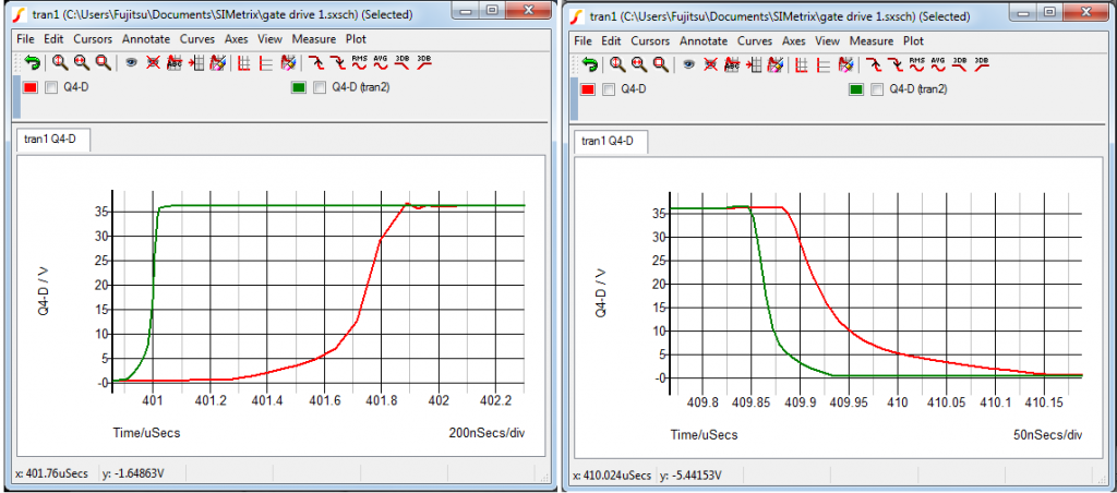
    With the additional 2 transistors shown earlier, I now added a resistor in series with each Gate.

    Green plot: R = 1-ohm
    Red plot: R = 100-ohms

    The gate resistance results in substantial degradation of the turn-on and turn-off times. I think it is better to use a ferrite bead on each Gate to suppress potential oscillations.

    Lester444
    Last edited by Lester444; 12-10-2012, 12:17 PM.

    Leave a comment:


  • JohnStone
    replied
    Originally posted by Lester444 View Post
    .... I ran some circuit simulations and I saw that the addition of 2 transistors can boost the LM555 PWM driver resulting in much faster switching speeds.....
    Hi Lester,
    thanks for your contribution!!! I will try this Symetrix simulation as well. Up to now I tried with LTspice but did not succeed to add the componentes required into the library.

    Addition to your schematic:
    It is desirable to add ca. 10Ohm resistor to any gate stub in order to prevent oscilations. Would you please post a simulation with this addition in order to show what difference we can expect?
    Reason: Simulation might not show that because you did not add the inductivity of the wires. It accounts for 0.00 mm wire lenth. Any inch of wire adds some nH and the FET possibly could oscillate then along the inherent gate cap.
    Naturally FETs are extremely fast in switching matters (picoseconds possible) if they were not loaded with the plague of inherent gate capacitance. Only due to this cap we suffer of those limitation defined in datasheet. In case of oscillations that specification is not the limitation at all. This means that though a FET is specified for a certain switching (controllable) speed it will easily be able to oscillate at much higher frequency - but not controllable.

    Slow scopes will not show up these oscillations.
    JohnS
    Last edited by JohnStone; 12-10-2012, 10:11 AM.

    Leave a comment:


  • Donald Haas
    replied
    1st test with PWM

    Hi All,

    I have a little beginner stuff to report.

    I ordered specified parts which havn't come yet.

    I set up a PWM circuit using my signal gen.
    Was able to adjust duty cycle and frequency.
    The sig gen puts out about 11vdc so I used that to puse the gate on a big
    mosfet.
    Wound a coil on a a plastic 1.5in pipe.
    3 layers of 120turns of #20awg.

    powered the coil with a 12v, 7ah sla batt.

    I saw most of what ufo said would be desirable.

    Solidly lit, very bright bulb at about 650hz, 30% duty cycle.

    Also a Neon pulsing purple and on to bright orange to very bright orangy solid purple.

    Tried it with a 12volt motor and it ran very little but made a lot of oscilliatory noises.

    The coil was warm, about 120F regardless of how the layers were hooked.
    One layer is 2.2ohms.

    I feel very fortunate to be part of this and have ordered three small motors to
    make a gen set and also hope to go big with the 12-12-12 plans.

    Thankyou all for being here, especially UFOPOLITICS.

    I hope and pray that your security is established.

    Mine is by faith in God. There is no darkness in Him at all.

    bro d

    Leave a comment:


  • Lester444
    replied
    Greetings UFO, JohnStone, All,

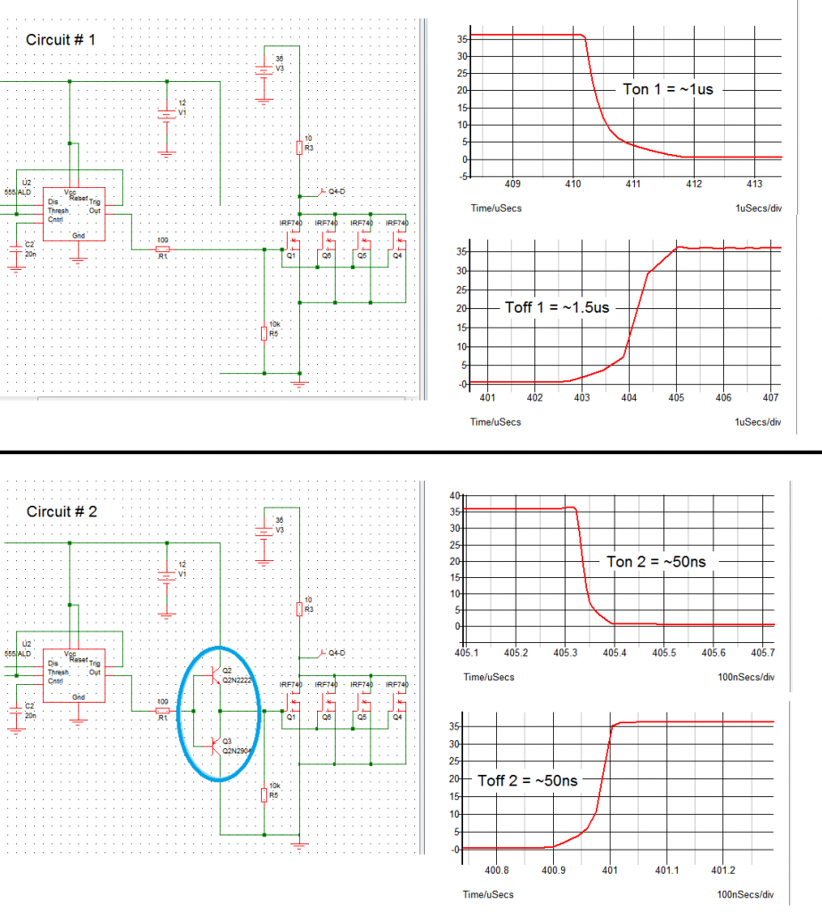
    I see that some folks here are trying to run FETs in parallel and as a result of this the turn-on and turn-off times are slowed down significantly. I ran some circuit simulations and I saw that the addition of 2 transistors can boost the LM555 PWM driver resulting in much faster switching speeds. Results shown below. The plots were taken from the Drain terminals of the FETs, 10-ohm resistor is used as a load instead of the coil.

    I have used 4x IRF740 in the simulations and free Simetrix simulator software. Analog Circuit Simulation Software from SIMetrix Technologies - SPICE

    I have posted the circuit below in case someone needs it to further their experiments. Of course good construction techniques are still required as what JohnStone has mentioned.

    Good luck to all and specially to you UFO, and may the radiant princess light your path always!!

    Sincerely,

    Lester444

    Leave a comment:


  • JohnStone
    replied
    Originally posted by boguslaw View Post
    Could you explain it a bit simpler , please ? My mosfet has many Qg = total gate charge , so should I add 10 those values and then compute the time required for my driver to charge them ?
    Like t = Q/I where Q is total charge, I current pulse output of driver (6A in my case) ?
    Then should I compare it to requested switching times ?

    Is this correct or I didn't understood your explanation ?
    Forget for a while the FET. You charge 10nF by 6A from 0V up to i.e. 6V for FET being fully open. It can't be explained easyier.

    You might want to get more knowledge by an online circuit simulator like Circuit Simulator Applet and there are plenty of others available. Get a current source, and a cap . Configure both and start simulation. You will learn a lot by charging and discharging the cap.
    Sorry - no simpler way available than hands on.
    JohnS

    Leave a comment:


  • boguslaw
    replied
    Originally posted by JohnStone View Post
    this doc as well.
    Could you explain it a bit simpler , please ? My mosfet has many Qg = total gate charge , so should I add 10 those values and then compute the time required for my driver to charge them ?
    Like t = Q/I where Q is total charge, I current pulse output of driver (6A in my case) ?
    Then should I compare it to requested switching times ?

    Is this correct or I didn't understood your explanation ?

    Leave a comment:


  • JohnStone
    replied
    Originally posted by [email protected] View Post
    .....
    The goal of my current project is to obtain potential from a battery w/o current flow. According to Bearden this necessitates switching with 1us (or faster) ON time. If my math is right, a 250Hz frequency and a duty cycle of less than 25% will gives me this.

    Is the gate cap something intrigal to the FET (built in), or is it something we add? If it a cap that I have to add, what size and type would you suggest for this particular application?....
    Oh yes! Now I remember! Sorry for that.
    Regarding 250KHz. It is for 50% duty cycle. If you reduce the duty cycle you will get no clear signal at output. The opto will not forward your control signal aas you intend to have it. But please test it before - usually they exceed the spec considerably.
    Why not start without optos in order to learn how FETs behave. Test with resistors as load before. Many replicators do too many staps as one and get a bloody nose. Please do it step by step.
    • drive ONE FET up to 1 MHz with resisor load.
    • dto. with moderate coil
    • drive several FETs to 1 MHz
    • dto. with bigger coil
    • add opto separation and verify if you get same results like before

    but it willl not help if you have a lazy driving.

    The gate cap IS DEFINITELY an inherent plague of FET technology. You can calculate conforming my advice to Boguslaw how many coulmbs you move at 1 MHz back and forth - it is a considerable amount. So please do it step by step.
    Please obey old Roman and Habsburg rule: "divide et impera" = "devide and role". It is true in this case as well.
    JohnS

    Leave a comment:


  • john_g
    replied
    Originally posted by Ufopolitics View Post
    Hello Donald Haas,

    That FET looks ok, is fast (RDS On 0.45)...but make sure the 10A are linear rating, as "Pulsed Drain Current" (PDC) they should mark higher...

    I use the NTE 2397 and note on the linked pdf that its PDC is 40 A
    The Ultrafast Rectifiers I use are UF505/NTE576
    Those are the best so far...

    Regards


    Ufopolitics
    Hi Ufopolitics

    In your video Defining RE field Pt 2, you had a dual oscillator pulsing in anti phase: is this really what we should be striving for? Or was that just for the video?

    I think I may have blown my PWM last night, but I was driving a motor off an inductor which has an over winding of finer wire. What was interesting, is that connecting the (transformer) output from the fine wire to the input of the motor caused an increase in RPM. The unit was driven by the PWM.


    Really looking forward to 12-12-12, thanks so much for your insight.

    Regards

    John

    Leave a comment:


  • bobfrench@fastmail.fm
    replied
    Fast switching

    Johns,

    The goal of my current project is to obtain potential from a battery w/o current flow. According to Bearden this necessitates switching with 1us (or faster) ON time. If my math is right, a 250Hz frequency and a duty cycle of less than 25% will gives me this.

    Is the gate cap something intrigal to the FET (built in), or is it something we add? If it a cap that I have to add, what size and type would you suggest for this particular application?

    Thanks,

    Bob


    [QUOTE=JohnStone;217605]
    Originally posted by [email protected] View Post
    So if I run the FOD, etc., at 250kHz, will it allow a duty cycle of 25% or less? Then I could have a 1 micro second, or less, ON time. What size gate cap would you suggest in this particular situation?

    I may get this project tried yet. Thanks for your help.

    Bob[/QUOTE

    Offitial facts:
    The opto is the slowest link in the chain and the FET driver behind will not switch more pulses per second than 250KHz. But those pulses have very steep slopes and those are a value in themselves for OU.

    Inofficial facts:
    But please note: The manufacturer garantees that the devices will perform at 250KHz. That is the max. they guerantee. But you as applicator stay on the other side and there you are told that they will exeed this limit for sure. Manufacturers can't avoid it as the technologies applied enable faster components than at initial launch some years ago. So be of good mood and check what FODs can do for you.

    Question: Why do you intend to switch so fast. The motor windings will not account for it. They will ignore it like your ears the ultrasound of bats.


    The gate cap is inherent and can't be avoided - it is a side effect of FET technology. You can get rid of a tick but not of the gate cap. It is definitley not helpful or intended but present. You must live with it and try to make it harmelss for your application. You do this i.e. by applying a good driver in order to charge/discharge it as quick as possible. Regard it like slack in mechanic device.

    Leave a comment:


  • JohnStone
    replied
    Originally posted by boguslaw View Post
    JohnStone

    I need a bit of help....
    My I ask you where I can find information about how to compute the required mosfet driver pulsed amperage to fill gates of some mosfets placed in parallel like 5 for example ? I would like to try TC4420 to drive at least 5 -10 mosfets to get lowered Rds resistance (like Ismael Aviso did btw). Thank You for any help.
    this doc as well.

    Leave a comment:


  • Donald Haas
    replied
    NTE 2397 equivalent mosfet for 89 cents

    UFO said:
    I use the NTE 2397 and note on the linked pdf that its PDC is 40 A

    From Jameco the equal mosfet according to data sheet.

    TRANSISTOR, IRF740, 20count $.8900 $17.80 12/07/12

    The are $5 and up most places.

    bro d

    Leave a comment:


  • boguslaw
    replied
    JohnStone

    I need a bit of help....
    My I ask you where I can find information about how to compute the required mosfet driver pulsed amperage to fill gates of some mosfets placed in parallel like 5 for example ? I would like to try TC4420 to drive at least 5 -10 mosfets to get lowered Rds resistance (like Ismael Aviso did btw). Thank You for any help.

    Leave a comment:


  • JohnStone
    replied
    [[email protected];217543] So if I run the FOD, etc., at 250kHz, will it allow a duty cycle of 25% or less? Then I could have a 1 micro second, or less, ON time. What size gate cap would you suggest in this particular situation?

    I may get this project tried yet. Thanks for your help.

    Bob[/QUOTE

    Offitial facts:
    The opto is the slowest link in the chain and the FET driver behind will not switch more pulses per second than 250KHz. But those pulses have very steep slopes and those are a value in themselves for OU.

    Inofficial facts:
    But please note: The manufacturer garantees that the devices will perform at 250KHz. That is the max. they guerantee. But you as applicator stay on the other side and there you are told that they will exeed this limit for sure. Manufacturers can't avoid it as the technologies applied enable faster components than at initial launch some years ago. So be of good mood and check what FODs can do for you.

    Question: Why do you intend to switch so fast. The motor windings will not account for it. They will ignore it like your ears the ultrasound of bats.


    The gate cap is inherent and can't be avoided - it is a side effect of FET technology. You can get rid of a tick but not of the gate cap. It is definitley not helpful or intended but present. You must live with it and try to make it harmelss for your application. You do this i.e. by applying a good driver in order to charge/discharge it as quick as possible. Regard it like slack in mechanic device.

    Leave a comment:


  • Ufopolitics
    replied
    Hello Donald

    Originally posted by Donald Haas View Post
    Edited circuit shows output diodes that are not numbered or valued.

    UFO calls them fast switchers, 400v and up.
    Need a part number or info if someone could help.

    these mosfets look ok?
    Mouser #: 511-STP11NM60ND
    100% avalanche tested
    RDS .45
    600v, 10a

    Many thanks,

    bro d
    Hello Donald Haas,

    That FET looks ok, is fast (RDS On 0.45)...but make sure the 10A are linear rating, as "Pulsed Drain Current" (PDC) they should mark higher...

    I use the NTE 2397 and note on the linked pdf that its PDC is 40 A
    The Ultrafast Rectifiers I use are UF505/NTE576
    Those are the best so far...

    Regards


    Ufopolitics

    Leave a comment:


  • Donald Haas
    replied
    Found diodes at mouser

    NTE576

    bro d

    Leave a comment:

Working...
X