
warrensk
No, straight DC is not the plan. John Stone has stated many times and UFO has stated this again today, that we will need bigger, faster and altogether more robust equipment to run the 56 frame motors. It has been stated many times also that the circuit you are building is for learning and small motors. Ufo and J.S. will tell you what the net requirements are when that is known. One note also is that if you read the thread, that all first runs of any motor was on straight DC so as to eliminate confusion.
Dana
-
Trouble with site
Hi All,
I've had endless problems with using Evergetic Forum.
Aaron says he knows of no one having similar problems.
When I submit a post the response page won't come up.
So I try again and same result.
Hence duplicate postings.
Today one place said I was the last poster on this thread and the thread did not show the post. Then it shows two posts after I spend 10mins trying to log in. Maybe someone has a better understanding of this than I.
Goofy stuff!
bro d
Leave a comment:
-
PWM + asymmetric motor = ?
Hello, After hearing the good news from UFO on the other forum....I am wondering if this PWM circuit (that i just ordered all the parts for) is what is later on going to run these asymmetrical motors more efficiently...?
These circuits allow for very fast switching time to basically only let potential charge the coil's resulting in the magnetic field charge and discharge resulting in RE without the classical discharging of a battery...please correct me if I am wrong. UFO is running his motor straight DC, not pulsed so far. Just wondering if this is what the plan is for the future. Either way I am gearing up.
Great thanks to ALL especially UFOPOLITICS for inspiring many to inspire others. May we all spread this beautiful (radiant) light for others to see the TRUTH.
Warmest regards,
WarrenLeave a comment:
-
Donald HaasOriginally posted by Donald Haas
Good to see you are making progress and going slowly. The middle pin of the pot on that circuit goes to pin 7 on the pot and the outer pins on the pot go to 1K resistors. If this causes wrong direction when turning pot, reverse the outer two and correct dial rotation. Coils should be air core and 1 OHM. As to the frequency, at 12v, this will just get the circuit going. You may be seeing a small cold side frequency because you are not feeding it enough. Go to 18 or 24 volts on the fets and watch the show. Start with both pots down, turn duty to 50% and slowly increase frequency.
Have fun,
DanaLeave a comment:
-
1st attempt with UFO's circuit
Hi All,
I want to go through the learning process carefully in able to have it right when it's time for the Imperial build.
Just got the recommended parts for the Lestter44 corected UFO basic circuit.
Breadboarded it last night.
I can not get the neon to flash but it will light to different degress of solid orange.
Can't get the cfl bulb (13w) to light solid but will flash.
My coils are (1) #20awg, 3 layers, 120T per layer, 1.5 in core.
(2) #17awg, 3 layers, 120T per layer, 2.5 in core.
The input amp from 12v batt for #1 coil is .016a, for #2 coil is .031a
Scope shows duty cyle of close to 100% when pot is close to minimum and will fry neon.
I need verification of how the pot is hooked.
Are all three legs hooked?
Not sure of the symbology on that pot. Three inputs to pot. ???
The cold side frequency is far less the the hot side.
Isn't this backwards? I tried hooking the coil both ways polaritywise.
I would appreciated any insights.
Retired with machine shop equipment, so should be able to get it happening.
I now have 3 goldmine motors to modify. Plenty to do.
I've done a lot of Bedini and fuelless building but this is a new approach.
Thanks for being here.
bro dLeave a comment:
-
Thanks johnstone,
That was very helpful, I will get to work ASAP. It sounds like this is something I will enjoy making and especially upgrading! Here comes some radiant energy!
Looking forward to some more disclosure today,
WarrenLeave a comment:
-
-
JohnStone,
It is normal practice to put big capacitor (500uF~1,000uF) across battery BUT place this cap very close to the Source terminal of FET and the coil, away from the actual battery. This cap will act like a low impedance voltage source and will greatly improve switching performance AND prevent possible unwanted oscillations.
Just my input. I have worked with similar high-current pulses in the past.
Leave a comment:
-
Hi warrensk,Originally posted by warrensk View Post
In order to understand the "mechanics" you shall imagine a hammer hitting a nail. A hammer made of rubber (flat slops, slow switching) will not have suffitient impact. A real hammer made out of steel 1/2 pound will give an impact of about 8 tons max. for short time (steep edges for some ms) - depending on your muscles of course.
There is no need to operate the hammer with 20KHz in order to drive a nail into wood. It will suffice to hit every two seconds but with proper impact.
Of course it will be the optimum in order to have a pulser being able to pulse up to 100A 20GHz (like Huchinson). In reality everybody has his limits in funds, skills, time left ......
My suggestion to drive a FET with 555 directly is the first step for low skills and low budget.
Recently Lester444 posted (thanks!) a remarkable enhancement with 2 additional transistors along IRF740 (10A/400V/30ns)
Next enhancement can be to use dedicated drivers.
Next step.....
Choose your way.
What I stress again and again is that even with second level components you can build remarkable pulsers if you obey using SHORT wires and massive bus bars at FETS (S/D). A highest level driver being 20cm apart from the FET will be third level in overall function.
The first steps will be to learn and you will get lot of skills operating the basic UFO schematic, my basic one or that enhanced from Lester444. There is an African saying: Arriving is built out of single steps - especially the first one.
Ufo never requested pulses in MHz range. Do not confuse the other discussion requesting MHz pulses. That relates to a notion from Tom Bearden and is not related to pulsing UFO motors. Bearden talks of separating longitudinal and transversal waves because of differnt latency in conducting materials.
Regarding FETs: Everybody has different sources available. PC-PSUs, shops, friends ...... So there is no general recommendation. Why not using IRF740 or other types posted or from scavenged PC PSU? It will be no problem at all to replace them by better ones - but please start. The only real minimum requirement is Vds 400...600V /RdsON below 0.5 Ohm / switching time faster than 100ns. Those values are for small setups.
Of course pulsing Imperial 56 frame motor is a very different category!
Please start with material readily available.
You are a lucky owner of a scope! And you can use simetrix simulator. So why not start simulating / building / checking with scope?
Regarding gate cap: It is a inherent plague of FET technology and NO part of your schematic. There are additional caps in a FET and in sum we need to account for ca. 10nF. The FET will switch along real charged voltage in this gate cap. Data sheets account for about 10nF and 10Ohm resitor between driver and gate. They account for about 10V charge in order to arrive minimum RDSON.
ESSENTIAL:- same length
- Check for spurious oscillations at switching edges. If oscillations found or no scope available add a 10...30 Ohm resistor between driver and each individual FET. It is better to have edges a bit degraded than malfunction.
Omitting those essential will degrade ANY superiour component considerably.
rgds JohnLeave a comment:
-
Hey Johnstone,
I tried to PM you but your inbox is full. I have been following for quite sometime and have been trying to keep up with all the information posted. I want to build a PWM to follow along but am a little confused regarding how important switching times are and capacitances within the FETS gate's....I have a Spectrum analyzer and an oscilloscope so I am ready and able.
Is there a specific FET that everyone likes/is easy to get?
Can these PWM go into the Mhz range...say 2-13Mhz?
I am also interested in how this RE manifests itself depending on different coil geometries so a PWM that goes a range of frequencies would allow for more experimentation. You can PM me and we can also get back to each other by email.
Thanks,
WarrenLeave a comment:
-
Hi Lester!Originally posted by Lester444 View Post
Thanks for the recent plots. As we can see, a resistance between 10..30 Ohm has moderate drawbacks. The shorter the wires are the less damping resistance we need and the steeper the edges can perform.
Thanks for contribution!
@Boguslaw: I tried the simetrix simulator as well and I recommend it. It is very professional and no dirty "me too" service.
rgds JohnSLeave a comment:
-
Hi dllabarre,Originally posted by dllabarre View Post
There are several stages to perform.
1. Starting from the vid from P. Lindemann "The secrets of electic motors" we see that a motor is driven by magnetics but there no direct handshake between electric input power and mech. output power.
2. UFO shows how to convert DC motors to higher performance an OU (asymmetric)
3. Along UFO motor we can harvest a certain amount of energy at the second brush set.
4. The notions above perform as ultimate prime mover and can drive state of the art gen heads.
5. To come: Modified asymmetric generators in order to increase COP considerably.
The construction of the coils is no secret. This item was discussed in great detail at the beginning of the thread. You might want to search for "coil" in this thread in order to find out where to read in detail.
The major requirement is to get the resistance of the coil - due to different requirements - in the range of 1 Ohm.
Please comprehend the matter as a series of puzzle parts to be assembled. Do not try to jump several steps at once as long you need to learn basics of this technology. It is i.e. better to have a dead simple pulser working initially than a sophisticated one never working.
rgds JohnSLeave a comment:
-
Hi everyone.
I spent several hours today trying to catch up.
What I gather is this circuit will be used to power an electrical motor using cold electricity that is converted to hot electricity to actually power the motor and this motor will turn a generator creating regular MAINS electricity. Am I close?
I saw several videos, I have the 555 timer circuit and picked up the parts on my way home today.
What I missed was the construction of the coil?
Can someone post a link or directions to wind the coil?
wire size, coil form size, number of turns/layer, number of layers, bifilar side-by-side wound as a pair, etc.
Any help will be grateful.Leave a comment:
-
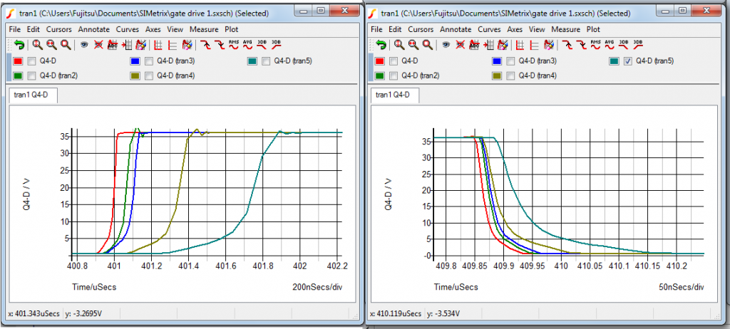
Here's how it came out with various resistances at the gates:
1R 10R 20R 50R 100R
I do agree that circuit stability becomes very important as switching speeds go faster. At some point a dedicated PCB layout would be needed since jumper-type wiring will no longer work. This is already in the RF realm and probably beyond the understanding of a lot of folks here. We also need a different circuit simulator for that.
Leave a comment:
-
Hi Lester,- A beat will increase the inductance and as such might reduce the oscillating frequency but it will very possibly not kill them.
- I agree with you regarding substantial drawback but at teribel wireing qualtiy even 100R might be necessary inorder to ficht against oscillations.
- As gate resistance usually 30 Ohm will be used - maximum. Would you please add a simulation with 10 Ohm. I feel the deviation will be acceptable.
- The shorter the connections the less damping by Rgate we need. The Rgate can not be calculated exactly in advance. It needs to be tuned individually to every setup.
If someone has no assets in order to detect oscillations he will possibly get wrong results. Therefore those guys shall add a 10 Ohm resistor first and if he gets reasonable performance he shall try without Rg for comparison.
Thanks for your contribution!
Here a wire calculator. If you like you could add the corresponding inductance to the wires (i.e. 20cm / FETgate ->driver and FETsource-> GND of driver and) check for oscillations. You will fight with about 2 X 300nH.
JohnSLast edited by JohnStone; 12-10-2012, 01:01 PM.Leave a comment:
Leave a comment: