
Garry
If it is time and money you want to save, as all of us do, just use the arduino and monsters and get on with the enjoyment of it.
Dana
-
pulser
@all
I have finished my third motor replication and have read through the thread from beginning to end. I have seen a number of changes concerning pulsers and am wondering how to proceed. I have all of the materials to complete the simple 555 pulser that ufo recommends on post 1543 except for the non polarized 1000 uf 50 volt capacitor which I seem to be having a difficult time finding a source for. Are we still using this pulser or have the arduino and monster drivers completely replaced this pulser. If so I would rather order the monster driver pcbs an populate them. Just trying to get my bearings for the next step without spending time on something unnecessary. Thanks in advance for any advice.
GarryLeave a comment:
-
John Stone data aquisition unit
We have been thinking about the wonderful sensor plan than John Stone posted http://www.energeticforum.com/237547-post2267.html
Thought we would break it down one sensor at a time to understand completely what is going on. Then we will combine all into one script.
First look was the Temperature sensor (two TMP102 units) ADD0 of one connected to GND the other to V+ (NOTE: the V+ from both units needs to connect to the +3.3V supply of the Arduino NOT the +5V bus) all other connections are standard I2C. The SCL connects to Analog in A5 ~ SDA connects to Analog in A4 ~ The Arduino code to run two sensors can be found at https://www.dropbox.com/s/qpxw78e55v571q3/TMP102_Digital_Temperature_SensorO.ino
Will play with the line sensor next to look at the RPM .
Hitby13kw
Research continues, Back to the bench . . .Leave a comment:
-
Soldering.
Thanks Soo much John Stone, am still waiting on 100Nf caps. i thought on the monster pics it showed ceramics, but i had a niggling voice in my head that DANA said all caps were Electrolitic, so went back through posts to confirm.
Caps should be here tuesday, sorry about that.
Kogs pm'd me with some soldering tutorials, Thanks Kogs, and i have ordered a digital 60 w solder station, with tips, should be here tues as well.
After watching the tutorials, i was heading for a very Frustrating and difficult time making these boards with what i had.
Thanks Everyone, Warm Regards Cornboy.
Leave a comment:
-
Instructable 5V1 - PSU
Our friend Cornboy started building his six monster drivers. I will assist him publicly step by step and all others are invited to watch and follow the instructions.
The procedure will be like this:- Assemble and solder one functional block at OHNE singel PCB
- Test it and learn what went wrong.
- Assemble and solder same functional block at other PCBs, apply what you learned and test them as well.
We will check the functional block step for step proceding from input along all important components to desired output.
In this session we will assemble and test the PSU part.

1.
Assemble and solder all parts you see in circuit diagram above. Please assemble electrolitic caps thoroghly and look for polarity. If assembled in reverse they can explode if powered. Double check polarity!

If you intend to assemble tantalum caps - beware! They are not made for PSUs and may explode even if assembled with correct polarity!
Safety: It is generally recommended to wear safety glasses at very first power on. If you decide to neglect this hint - please keep eyes away from top of PCB in order to let caps shoot like little rockets to ceiling.
2.
We use an external power supply. It can be double lead battery (24V....30V), lab PSU or simple wall charger.
Safety: Especially if using lead batteries or worse Lipos please insert a fuse in + lead (i.e. car fuse). Else any short circuit might set your place in fire or explode batteries.
Safety: Provide additionaly a switch in + lead in order to switch off instantly if your circuit behaves abnormally.
Input voltage shall be 15V minimum! Upper limit is about 30V. Do not apply more - else voltage regulators might explode. They are rated absolute maximum for 36V. Regulators are very ruged but at overvoltage they get nasty and picky.
Check for PSU polarity. D10 is a protection diode. It will block current if external PSU connected in reverse.
Connect external power supply.
Check fo any abnormal noise, smoke. Touch components with your hand and check for hot parts. None shall get hot just now.
3.
Connect GND of your meter to GND on connector X8 and let it sit there for rest of test procedure. You will move the active probe only.
Measure input voltage at connector X8 and check if it is still around the value you measured before in idle mode.
If you read some few volts or less you have a short circuit. Switch off instantly and check.
BTW: If you are happy to own a scope please us it. In rare cases regulators tent to oscillate. Then you can detect this failure instantly.
4.
Measure input voltage after D10 and check if you read about same voltage like before (0.6V less)
5.
Measure voltage at input of IC6 (7812) same like before.
Measure voltage at output of IC6 (7812). It shall read 12V +- 10%.
If you read considerably more you have a diconnected GND at IC6.
6.
Measure voltage at input of IC5 (7805) same like before.
Measure voltage at output of IC5 (7812). It shall read 5V +- 10%.
If you read considerably more you have a diconnected GND at IC5.
7.
Perform a load test at 5V output by connecting a resistor of about 100 Ohm to 5V (exact value is not essential)
Check voltages like above (3. ... 6.) They shall not change considerably (some few mV only) at regulator outputs (12v / 5V)
If you performed above procedure successfully, please assemble all other boerds like above and test like above.
OK, Cornboy? If you are ready please order next instructable. We will focus on opto input circuit.
Cheers
John StoneLeave a comment:
-
Hi guys
Johnstone I like that setup as well. I have no experience programming, and things are slow to grasp for me , but even I have been able to slowly find a spot to start working.
I just was able to get/find a program that prints my headers on excell. I thought that would be easy, but , I'm telling you the adafruit data logger example does not work for me. Anyway, finally logging and writing to excell, with nice headers, graphs and spreadsheets.
I have most of those components, no ir interrupt, I am looking forward to finally start trying to use some of these sensors.Leave a comment:
-
@Garry, Ufo
As soon we contact a wire electrically with our data aquisition system we are prone to malicious influences. This relates mainly to voltage measurements. For current we have those nice Allegro ASCxxx breakout boards - fortunately. Temperature measurments will have no electrical contact and will be handled via I2C. And yes we will have 2 ADC channels left (future expansion) and we can use them separately or as one single differential input.
We need to prevent as many disturbanceies as possible because most builders are not able to valuate the real precision by their own. I can do it for my setup but not remotely. Therefore a second level optimum setup might be more helpful than first grade solutions. I suggest a rugged and easy to achieve setup in order to prevent any hiddeen "guess-work".
In professional world there are handy solutions available for all sorts of galvanical isolations. Unfortunately those parts explode our budget and expertise completely.
Apart that we can not expect all contributors to handle small surface mount devices by their own. There exist very nice isolators for I2C but no breakout boards avaliable. And we need additional islolated DC/DC . Hence this solution will be an additional obstacle.
I feel isolation via cheap BT I/F (com port mode) will be the best way.
I will complete a doc next days and I will lay out all details there along explanations. We surely will discuss it later on.
BTW: For final solutions it is desirable to have a highly sophisticated setup saving effort and cost. But if we negotiate effort for final sophistications and the expectation that we will possibly get several modifications I vote for more simple solutions in first step.
I.e. some of us still struggle on FET operations and we can not load all with sophisticated solutions.
My focus is to enable all following the path.
JSLast edited by JohnStone; 08-15-2013, 08:53 AM.Leave a comment:
-
Four Channels...Excellent Set!
Originally posted by GChilders View Post
Hello Garry,
I see A0, A1,A2,A3...as Four Channels for Four ac5714 Outputs on the ADS1115...am I right Sir John Stone?
Or like you wrote Garry...maybe one ac5714 could handle more than one signal read out.
Excellent Set Up!...and like He wrote...this is not the final and completed one...
It is very nice to see where we are getting at...very sophisticated and Elegant Set Up...plus precision at its Max Expression...
Warm regards
UfopoliticsLeave a comment:
-
Data Aquisition Setup
Dear John Stone,
I like your setup, but I do not see much in the way of amps in, amps out, volts in, volts out. Are you continuing to recommend the analog sensors that you recommended previously or is the ac5714 capable of handling all of this information, or do we need multiple ac5714 modules.
Cheers,
GarryLeave a comment:
-
Please do not rush and buy materials for this data aquisition system - not yet.
The pic above is just a first glance. It does not get much more sophistcated but I will do more drawings showing clearly how to wire and how to shield.
My suggestion negotiates between cost, performance and ease for building and use and global availability as well.
Anybody is allowed to do it differently but he needs to know exactly what he does and needs to account for drawbacks.
Please admit that an electonic circuit is only one plane of the whole crystal. A circuit digram does not show lots of artifacts that surely take place. There is an HF and mechanic plane present as well. In order to account for these planes I will add some additional drawings.
It will be essential to have shielded cables from Arduino to sensors. Initially I preferred shielded CAT5 network patch cables. But this seems to be an European artifact. In North America networks run unshielded (different physics over there??? ). Hence you might have difficulties to get such cables.
As alternative I will suggest USB cables. They are shielded, readily available und cheap.
Stay tuned for more details. I will submit a kind of picture book as detailled instructable.
JSLast edited by JohnStone; 08-14-2013, 11:14 AM.Leave a comment:
-
Hello my dear friend John Stone, many thanks for the scheme.Originally posted by JohnStone View Post
Warmest regards
Nameste
lightLeave a comment:
-
Here my suggestion for a data aquisition setup FOR ALL. It is not final but I want to show a preview.

ENJOY
Some final addons are necessary.
The whole system will be supplied by a socket charger.
All data red will be displayed at PC via BT. Local display possible as well.
Prog. download via USB cable. Later on it shall be disconnected for SAFETY reasons.
JSLeave a comment:
-
Data Aquisition
Data aquisition is one major part of our research in order to prove the very special nature and advantage of UFO type motors. Fortunately we have plenty chances to perform but unfortunately not all are valuable.
- What we search for is a minimal system all members can get hold of but being expandable for possible later use.
- Apart that we need a certain precision and undisturbed repetition in order to avoid "guess-ware".
- Additional requirement: - having separated GNDs
Having those fact in view we cancel out lots of procedures. In example we can get plenty of nice breakout boards at ospark. But will everybody be able to buy all parts and solderthem in a relibale way (SMT = tiny and no through hole).
Having this in mind I scanned all possible sensor breakout boards at Adafruit, Pololu and Sprakfun. Fortunately allmost all boards selected can be obtained at one single source in my country (Watterott) - but much more expensive  than genuine sources in US.
Now let's look at awalk through to my thoughts for a concept:
1................................
It is desirable to have a dedicated display but for development of the data system itself it is very convenient to get data on PC because there is no additonal hurdle to display data there. A dedicted display can be added later on.
2..................................
Values to be red:- voltage in
- current in
- rpm
- temp
- torque or voltage out and amps out) :TBD
3. Values to be logged:- see above
- momentary power in
- energy in summed up
- momentary power out
- energy out summed up
3....................................
Precision of Arduino analog values might be minor - espacially if we require high range. Therefore I suggest using a I2C 16 ADC breakout board. 860 samples per second.

4 channels with progr. gain amplifier.
Here we can connect a voltage devider for input voltage and a current sensor (Allegro)

For rpm I suggest an optical sensor

being connected to Arduino interrupt directly. It will calculate corresponding rpm.
For temperature I suggest
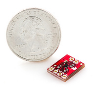
There are other temp boards available with contactless action:

4..................................
Major problem is the GND isolation from PC or other GNDs. There are means for isolating I2C but no breakout PCB available.
The only easy way will be:- To supply data system completely by a dedicated socket charger
- To add a cheap BT I/F to Arduino and route serial communication via BT instead USB.

- Setup at Arduino and PC are quite easy.
In the end we will still communicate via a com port - no difference to USB.
And you definitely have your beloved PC device extremely safe.
5.......................................
At 328 Arduino itself it is not accepted to operate USB AND BT at same time. They need to be switched somehow. Program download is possible via USB only!!!!!
But IF we use Arduino Leonardo-> it performs USB via dedicated HW -> freeing former true serial I/F as second one for our BT I/F.
At Arduino Leonardo (all with 32U4 processor) we will connect USB for program download only and disconnect it for real life and heavy use at our setup.
6.......................................
Arduino shall be mounted in a metal box for proper EMC shielding and Sensors shall be connected via cheap CAT5 Network cables for shielding as well.
7.....................................
Last but not least:
If you intend to operate a dedicated Display - disconnect BT I/F and add your preferred LCD along corresponding Arduino code
8......................................
Please do not add this data aquisition system to pulser. It will possibly work but will add additional complication. It is much more helpful to operate 2 Arduinos and get function soon - lessening obstacles.
------------
After plenty of head ash along internet search and digesting all possible setups for a data aqusition system I came to the suggestion above - data aquisiton for ALL. It is still affordable but requires no tiny SMT soldering and no puchase of different special components. Maintenance is easy if boards get defective.
All wiring can be documented by Fritzing SW
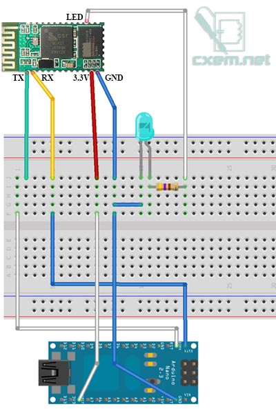
We can put together a clear purchase list as well.
If we decide to we can make a PCB at Oshpark for adding all those breakout borads in a repeatable way - for ALL.
There are some additional issues i.e. for measuring output power (safety!!!!). It will be solved with similar elegance. But please let us discuss this part 1 of my suggestion first.
Is this a way to go as reference for all?
Have you got additional good sources or brakout boards? lease suggest!
Please understand our task here is not building sophistecated or extrmely cheap electronics but using electronics as a tool only in order to focus an the major goal of these two threads.
JSLast edited by JohnStone; 08-12-2013, 08:14 PM.Leave a comment:
-
OSHPark board info
Hey Gang,
Ufo,
OshPark provides in lots of 3 PCBs. He said he may go down to ordering by 1 if he gets any volume. But we know you favor 4-stator systems, so the minimum order would be 4, but spares are nice I think as a quick solution to a burnt out board. So it looks like people should order 6. I can ask if he can do lots of 4...
You may notice the drill holes graphic. Since we must all assemble them by hand, that is the ticket. Any one doing surface mount out there yet where a robot plops all the parts down with the solder already on the board and then they just run them thru an oven yet? NO, Not yet I suspect
OshparkShare on the Monster driver worked, now available there also. Now on Page one, but it looks like it gets moved to the higher numbers as newer projects get accepted. Still available at the OSHPark Store and search on "John Stone" or "Monster Driver" -or- Monster Driver OSHPark Direct Link
Emailed Jim Neal, at [email protected] and he has already gotten 2 orders, YEH! International orders are NP! I believe OSHPark are out of Seattle WA.
@KOGS asked about a double layer of traces, Mr always thinking guy, so I asked "laen" and he responded in a way that will make everyone more interested...
Sampojo:
Here is a good technical question a forum member has asked. Since you only make 2 layer boards as your lowest option, on our single layer board, when I duped out the appropriate file, does that mean you made a duplicate of the one layer of traces over again on the board in your automated processes? This would be great if so, as some members have reported some traces burning up due to the load on their home manufactured PCBs, using these gerber files on their equipment...
-Laen
I _can_ definitely do that. It sounds like that would be desirable, so I'll make it happen.

Started assembling my first board.
That's all, folksLast edited by sampojo; 08-12-2013, 03:57 AM.Leave a comment:
Leave a comment: