This forum is preserved as a permanent archive. The community continues at eMedia Press.

Announcement

Collapse
No announcement yet.

My Motors got me to Tap into Radiant Energy

Collapse
X
 
  • Filter
  • Time
  • Show
Clear All
new posts

  • Hitby13kw
    replied
    OSH Park Monster Driver boards

    Cornboy,


    I have a question, placed an order with OSH Park for several boards (to compare them to my board) and paid them via PayPal back on 8/9 but have not gotten any response back from them. How long did it take for you to get your boards from them? And do you have a phone number for them (nothing on the website), Living in hope they will not let me down.

    Hitby13kw

    OSH Park update ~
    The Monster Driver boards went through The Store, which is a slightly different process which can take a couple of weeks. I should have those back and shipped by Monday.


    -Laen
    Last edited by Hitby13kw; 08-21-2013, 08:40 PM. Reason: update

    Leave a comment:


  • prochiro
    replied
    Cornboy
    Are those caps pointed in the correct direction as it is easy to reverse when looking at other side of board.
    Dana

    Leave a comment:


  • prochiro
    replied
    Cornboy
    make sure that the copper leads on that board are same as Monster v5.1 drawing. If it is then it may be solder overflow. This is tested by continuity check of copper leads. Some should go beep and some should not as per JS's v5.0 diagram. You will find your problem with a continuity checker.
    Dana

    Leave a comment:


  • Cornboy 555
    replied
    Bugger.

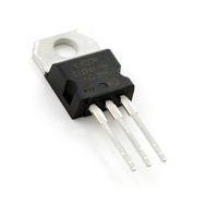
    Hello John Stone and all, new solder station works a treat, have completed first section and tested, nothing gets hot and all tests well, except for the 5v regulator.

    When tested it shows 12v in but 11v out , i thought i may have cooked it so i replaced it with another, but measured it first and output was 5v, when installed output is 11v , pulled it back out and output is 5v, wtf.

    Need suggestions, guy's, can't work it out, might i be doing something simple wrong?.

    Regards Cornboy.

    [IMG][/IMG]

    [IMG][/IMG]

    Leave a comment:


  • Hitby13kw
    replied
    John Stone data acquisition unit

    Had a chance to do some further testing, this week we got a chance to look into using the IR sensor from sparkfun https://www.sparkfun.com they offer this in three different formats:

    https://www.sparkfun.com/products/9453
    https://www.sparkfun.com/products/9454
    information could also be collected via the I2C bus - with the following sensor
    BOB-10901 VCNL4000 Infrared Proximity Breakout https://www.sparkfun.com/products/10901

    all three would be viable solutions, with reflective marks on the motor shaft to determine RPM, this is an adaptation of the code at Arduino Tachometer - Introduction | PyroElectro - News, Projects & Tutorials
    Please feel free to change, reuse and share this to fulfill your individual needs.


    The Arduino code to run an IR sensor to determine RPM is at https://www.dropbox.com/s/i59vg2dfhco0via/QRE1113_Tachometer.ino

    We plan to look at the 4 Channel ADC and Current sensor next, stay tuned . . .


    Hitby13kw

    Research continues, Back to the bench . . .

    Leave a comment:


  • JohnStone
    replied
    Temperature Sensors

    A: Pondering on temperature sensors and negotiating pro and cons:
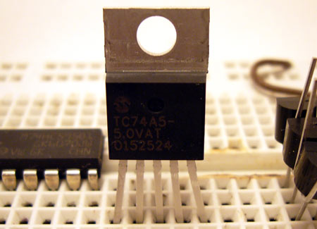
    1. TC74
    Through hole types are a dying race. Therefore we are restricted to some few models.
    But TC74 is readily available and cheap. But the metal tab is not isolated at the tab - in fact it is connected to GND pin 3. It requires thorough isolation by plastic distance spacers and isolating pad. But monting is very convenient for anybody.
    We can buy TC74 with several preprogrammed I2C addresses
    TC74A0-5.0VAT / TC74A1-5.0VAT ......

    2. Other through hole devices
    It will not help to load you with buying some few strange chips in PDIP housing anywhere and to find somebody writing control SW for it.

    3. I2C level shifter 3.3V/5.0V
    What about if we use I2C level converter 5V /3.3V along a simple 3.3V regulator.
    $6.95
    $1.95
    Then we can connect TMP102 from Sparkfun and any other future sensor with 3.3V. In fact it is cheaper than paying shipping costs to lots of alternative sources.
    I suggest to include the level shifter along 3.3V regulator in the control box and provide a cluster of USB jacks for 3.3 / 5V each. Mark them properly in order to not interchange 5.5/3.3 sensors.

    But please regard that TMP102 is difficult to mount at motor housing.

    Please ponder on those alternatives. We should get a common decision in order to have standard control SW. I myself still feel TC74 to be most convenient.

    B: USB jacks at motor side (UUT)
    The motor might vibrate strongly and USB connectors are not made for this operating mode. Having this fact in mind it would be advisable to cut connector at sensor side and solder wires to PCB directly. Please add strain relieve in order to protect cables from defects - ( i.e. use U shaped wire soldered on PCB and hot glue).

    JS
    Last edited by JohnStone; 08-20-2013, 05:52 AM.

    Leave a comment:


  • machinealive
    replied
    Hey JohnStone

    Nice pictures to help visualize everything. I'm sure glad we got ya here.

    I think I've finally got 1 analog temp sensor, and a digital hall sensor incorporated into my logger sketch. I finally was able to compile something that was ok.

    Now, hopefully it logs and prints right.
    The fun never ends.

    Still livin'
    Machine

    Leave a comment:


  • Cornboy 555
    replied
    Thankyou.

    Great Work John Stone, THANKS very much.

    Waemest Regards Cornboy.

    Leave a comment:


  • JohnStone
    replied
    Preliminary Document

    Hi friends,
    you will get now a very preliminary doc for the measurement system. Excuse please the raw state. It is late night now and I will have less time next month and I hesitate to let you wait for longer time.
    Therefore I ask you kindly to not believe all I wrote. UNderstand teh reasons and uintentions and use your brain. You will surely find some errors. Sorry for that.
    LN005 Data Aquisition System For Asymmetric Ufo Motors (V0.0)

    Read it, understand it, correct it, build it, enjoy.
    Cheers
    JS

    Leave a comment:


  • iankoglin
    replied
    G'day John
    Thanks I hope this works
    https://www.dropbox.com/s/ndf6rm8w2g...%20Ver1a.T3001
    Kindest Regards
    Kogs[/QUOTE][/QUOTE]

    Yes well. Now the link is ok now.

    I can not dig into calculations but I am pretty sure you can scale all timing relevant components.
    Pot = 5K (50K before)
    R5 = 100R (1K before)
    R7 = 100R (1k before)
    C1 = 100nF (10nF before)

    Try it. It will do fine.
    Cheers John


    Thanks John my friend as I said before you are a gem a rare one probably a red opal Please your PM's are full you need to empty some

    I will try it.
    Yesterday I could not wait I connected a normal 50k pot and was running my bike I stalled it and before I could turn it off the 2 1 Ohm resistors on the Monster burned and the machine stopped.
    Later I found the Battery is still fully charged I just cannot access any current from it I guess the BMS cut out and I cannot find where to reset it.

    I will try the changes you suggest to the Oscillator and replace the Lipo battery with some slab's, fit the twist throttle and see where it goes.
    Thanks a million
    Please thank your wife for lending you to us.
    We all on the these forums really appreciate what you are doing for us.

    Kindest Regards to both of you

    Kogs

    Leave a comment:


  • JohnStone
    replied
    Originally posted by Hitby13kw View Post
    .....First look was the Temperature sensor (two TMP102 units) ADD0 of one connected to GND the other to V+ (NOTE: the V+ from both units needs to connect to the +3.3V supply of the Arduino NOT the +5V bus) all other connections are standard I2C. .....
    Thanks for digging into matter as well. You are right TMP102 is a 3.3V chip. My error . I intend to suggest a 5V only system. Sparkfun use TMP102 chip from TI. TI offers very same device TMP101 for 5V. But I found no breakout PCB. Is any other sensor breakout with 5V available?
    The only non SMT sensor I found is TC74 from Microchip

    link
    link

    Thaks for your alert

    BTW: Still working at PDF doc for measurement system any spare minute.
    JS
    Last edited by JohnStone; 08-17-2013, 10:40 PM.

    Leave a comment:


  • GChilders
    replied
    @Cornboy,

    never mind I thought I remembered that somebody had asked this question and found out that it was you, and Kogs answered it.

    Thanks

    Garry

    Leave a comment:


  • GChilders
    replied
    test connectors

    @Cornboy,

    Where did you locate the k1xo2 k1x04 and k1x06 terminal tester strips. I have not been able to find any with the long leads on them in my google searchs.

    Cheers,

    Garry

    Leave a comment:


  • Cornboy 555
    replied
    Great.

    Originally posted by GChilders View Post
    @Dana

    Thanks Dana that's what I needed. I was just unsure of the pulser being completely replaced by the monster drivers or if there was still a function that it was fulfilling. I will order the pcbs and parts for the monster drivers today.

    Cheers,

    Garry


    That's Great Garry, thanks for joining in, in such a practical way.

    Warm Regards Cornboy.

    Leave a comment:


  • GChilders
    replied
    pulser

    @Dana

    Thanks Dana that's what I needed. I was just unsure of the pulser being completely replaced by the monster drivers or if there was still a function that it was fulfilling. I will order the pcbs and parts for the monster drivers today.

    Cheers,

    Garry

    Leave a comment:

Working...
X