
regarding test loop
@ufoPolitics
The test loop in a rough draft that you are talking about has already been built into the program. Once we establish a baseline for the motors in startup to idle mode we can uncomment this area to work with it. The method rpmCheck in the program does exactly this. After start up the motor loop calls rpm check to check the last two values in the rpm array and compares them to see if the motor is accelerating or decelerating and then checks to see if the motor is operating within the range of 3400 to 3800 rpms and trims the amount of the setting for the duty cycle and the wait periods depending on whether it is accelerating or decelerating and changes the wait periods and calls the motor speed ramp if necessary to give longer periods based on the level the rpms have fallen to. And it adjusts the current duty cycle to either speed up or slow down the motor if it is out of range. At this point we need to get each motor to a base line where we know how it will operate in the startup and idle modes. Once we have that nailed we can uncomment that area and begin to truly control the motor. I am anxious to get to that point. But first I think we need to find the baseline for each individual setup before we add that complication into the mix. One parameter at a time is the most solid way to go forward. Start with a reasonable voltage and test the motor with a reasonable amount of duty cycle adjust the duty cycle incrementally until the idle time for mode 1 and 4 are clearly within the range that we are looking for preferable on the high side between 3600 to 3800. Once we have the guys understanding how this affects their setups they will have a better idea of how the rpmCheck method works and they can then see how the motor speed ramp integrates to the rpm check method and we can fine tune the amounts of duty cycle additions in the rpm check method until we can have a smooth transition of power during load. But there is a learning curve to this. This will require a little understanding of the basic parameters before moving on to the more complex piece of the puzzle. I want to get everyone on the same page so that those that are starting now will be able to help others as their systems come on board. At this point we are still trying to find baseline settings. Once Dana and Hitby13KW have that nailed we can move on to the more interesting pieces of the design.
@cornboy
I love your monster it is truly a work of art. Mag3 is magnificent indeed. Well we had you in mind when we designed the motor control and are set for you to finish it and give it a go. Can't wait to see that bad boy kicking out the juice.
Cheers
Garry
-
Controlling Asymmetry...
Originally posted by GChilders View Post
Hello Gerry,
Thanks, I wanted to represent there what we've got so far...
The Left Diagram shows Volts versus Amp Draw, or Motor Consumption.
The Second Diagram shows Watts versus RPM's...or Motor Performance "Costs" (in Watts) to Us...
Eventually, We will need to start showing/making 3D Graphs/3D Curves, just because we need to include Time in all that Data shown...plus more Parameters to come.
Now, a simple Nature/Behavior of this Technology could be observed in any model, and just feeding it linear through any PSU...
When We start Motor, it demands High Amperage, since it is "filling up" all those empty coils...BUT, Once they are Energized, amperage starts reducing...without reducing Performance.
Now, based on this Typical Behavior...We need to keep developing a Method to full-fill this "Mode Operandum" .
In Future Designs, when we incorporate Capacitors parallel to Coils...we will ONLY need this High Starting Input...ONCE...during lifetime of Machine. But, right now, as we are at...we need to consider this approach every time we start this set up.
I would like You to consider...some "Testing Loop" within Software at starting Mode...where Signal starts at a High Duty Cycle...then read Speed through sensors, and as it reaches desired RPM's...Signal would start Slowly, decreasing Duty Cycle...to a minimum while Monitoring Speed not to fall below requirements, and keeping this "Low Signal" as a Minimal Duty Input.
This Loop will need to be "Invoked" every time we add a Load...or an Appliance Cycle, like an Air Conditioner...or Refrigeration Unit does Cycling Thermostat/Compressor...
An Important issue here: Mecc Alte or many other Generator Heads, could work with speeds Higher than 3600 RPM's...up to 3800...and Minimum 3200...so, this is a RANGE, and NOT a "Perfect and Unique" Steady 3600 RPM's parameter.
And this is very Important to understand by You Guys Testing this Set Up...because we could go 3800, or close by, say 3790...when Motor requires to "Fight" a bigger Load Generator Head is requesting...
On another Note...And this is beyond Your reach, (so far) Gerry...because it is not about Signal to FET's Gates...But...the High Voltage feed between Source-Drains...and John Stone and I discussed this possibility in past posts here.
It is about "Adjusting Voltage Feed" but not through an Electro-Mechanical Component like a Potentiometer...but through Electronics circuitry at Drain Source Feed...and, once we build this Circuit stage...then the low signals that Modulate it, would be incorporated to your codes...different Input Pin from Arduino...same Program.
And this should work Inversely with your Starting Loop...in order that at very sharp/short pulses (Lower Duty Cycles)...we can inject Higher Voltages at Source. This will create a Balance in Speed and Power...while reducing Amps.
But We will get there..."in time".
I see Your Codes as very flexible, and as you have pointed out....just by dialing 255 Duty...We will have a Quad Blink response...that could be "invoked" or "Call Back" at any time during Operation
I love Your dedication to this, and Thanks so much for such High Contribution to this very Important part of Our Development!
Warm Regards
UfopoliticsLast edited by Ufopolitics; 07-27-2013, 06:25 PM.Leave a comment:
-
stretching the signal
@ufoPolitics
nice graph. You are absolutely right about the signal needing to be stretched as you call it. As the duty cycle value is increased the time that the portion or the pulse wave allocated to the on or high portion of the square wave is increased or stretched while the off or low period is shortened until at 255 it is all high and there would be no low signal at all. And it may be counter intuitive but there may be a point where there is less over all consumption at a higher point than at a low. Right now everyone is increasing voltage in order to get rpms up. Increasing the duty cycle value may accomplish much more. It is possible at different times in start up and when running to increase or decrease the duty cycle to meet our needs as load conditions vary from light to heavy and back again. I recommend that the duty cycle by tuned in mode 1 and mode 4. This is our standard one pin driving one pin generating mode with 2 brush pair, 2 driving and 2 generating with 4 brush pair. This at idle at the target rpm of 3600 which is the target for the Mecce Alta. Once this is accomplished it should leave plenty of head room, so to speak, to kick in mode 3 or mode 5 which we have demonstrated can be changed on the fly with this new program. This will give us the awesome ability to shift to increased load increases of several thousands of watts and instantly change to meet that demand should the motor ever need it. I am encouraged by the testing at such a reduced duty cycle of 65 the motors although starved for power are almost keeping up with the full power of the blink four method. It could be that at 130 the increase in power will synchronize with the reduced time periods to produce even more efficiency that cannot be explained simply by the normal increase of power. Asymmetry as you have revealed to us has properties that are not explained through simple increase of power. I look forward to seeing what everyone will do with this and ways that it will point us to in uncharted areas.
@Sampojo
We all welcome any with anything to share to step up and bring that to the table. The software is open source and may be changed to suit anyone's needs. If you would like to design a particular piece it would be best to clear it through ufoPolitics, John Stone, or Dana First. I am a student of this technology and as such am learning at the feet of these great teachers a technology that I consider to be revolutionary.
@John Stone
The code for I2C is quite simple to write and would be a good choice for those who have not purchased sensors. It is a very good communication protocol especially if you are planning to populate with a lot of sensors that use the protocol. It only takes two wires and each sensor has an address that can be called to request the information in the register of that sensor to get the values stored there. The nice thing is that you can choose to update it whenever. Some of the sensors are not cheap by any stretch. If we could find a source for them that would offer discounts for good value it is definitely the way to go. I am not sure what sensors besides the temp sensors would be using this method. The amp and volt sensors in the link you provided seem to need the analog pins in order to work. Are there any that would work with I2C? What other sensors did you have in mind?
@Hitby13KW
I love the way you capture the information on your runs. It seems like you have integrated the information into a spread sheet and then sift through the reams of information to get the important changes. Good work and a good run with lots of valuable information there. Thanks for sending me the pm with your changes, it helped me assess the program and make some changes that will help everyone.
@Dana
Thank you for all of the feed back on your set up. You were the inspiration that got the ball rolling to create the program initially and your comments on the difficulty of working with the serial interface sent me back to the drawing board to create a truly simple interface. You guys are tearing it up in a good way.
Cheers
GarryLeave a comment:
-
@all
let me know if that link didn't work. I thought that I did it correctly but I thought I did it correctly the last time also.
Cheers
GarryLeave a comment:
-
bad link
@all
well here is the link, some malfunction I guess
Leave a comment:
-
rmcversion0.0.2
@all
Well I have completed the revision of RadiantMotorinoControlVersion0.0.2
and you can get it at this link.
https://www.dropbox.com/s/nm0b2dx9cz...rsion0_0_2beta.
I have revised the command to allow much easier control from the serial monitor provided by Arduino. No need to shift cases any longer and nothing requires more than three key strokes before hitting the enter key.
The new commands are in the new revision of the tutorial
Two other changes are in this version. The first is that the new variable startDutyCycle defaults to 130 instead of 65. It seems that the motor was under powered. this number can be completely changed before startup as the tutorial explains.
The other change was the delay period that Dana worked out to be 15 milliseconds is now in the code in the revision.
It is a work in progress and I do appreciate your patience in all of this.
cheers
GarryLeave a comment:
-
Originally posted by Cornboy 555 View Post
Cornboy, in the results I had posted the supply was a variable DC supply feed from the grid (that way we could give the fixed voltage in 10 Volt steps) I plan on redoing the test using batteries (it will be about 12V steps, but we all know that) - I suspect that the current readings may be different as the batteries can absorb any radiant versis the power supply has no idea what to do with it. We will see,
Research continues,
Hitby13kwLeave a comment:
-
Klein Crewst Factor
Hi John Stone,
Thanks for all your continuing contributions!
Connected with Klein regarding Crest Factor:
The Crest Factor on both the MM2000 and CL2000 True RMS meters is 3 to 1 at full scale and 6 to 1 at half scale.
Jeff Bentley
Klein Technical Support
IndianaBoysOriginally posted by JohnStone View PostLeave a comment:
-
update
@ Garry
Now your talking...
Changing things in code is lost with updated and not understood by many. This will put all on an even keel.
DanaLeave a comment:
-
quad blink vs rmc
@all
first the two methods were designed for completely different goals in mind. My desire to be able to control the speed of the motor for power generation is what lead me to this design and then that expanded to be able to create a test platform that would be able to dial back the amount of duty cycle that is being given to the motor.
To apply a more scientific comparison you must first start with a method that simulates the same events.
quad blink has four power periods for a 4 brush pair motor and 2 power periods for a 2 brush pair motor. in each of these the rotation is divided by four in the first and 2 in the second and the pulse given to that brush pair in the motor is full on for the entire time period that is allotted to that brush.
to accomplish a similar result with the rmc simply type 255 into the parameter that I have been showing everyone and you should get the exact same statistics that the quad blink program is getting both on mode 3 and mode 5, now why is this so. Because during the entire time period the pwm will not modulate the signal it will be at 5 volts throughout all off the time slices of the period. If you would check that you will I think see the exact same results. What we gain here is the ability to change that parameter and see if it is possible to have a more efficient use of the energy by reducing that number and retesting. Then we could examine mode 3 against mode 5 in a side by side comparison to see which is actually a more efficient use of the energy. None of us can know until real scientific method is applied as to which method will produce better results. If we start comparing apples to oranges it will not help us. To compare a single apple that is 2 inches in diameter to a single orange that is 4 inches in diameter and make the conclusion that all oranges are bigger than all apples is a huge mistake. Only by comparing thousands of apples to thousands of oranges can we come to a conclusion. Now I think that oranges may be larger than apples but I do not know for sure.
The multipulse method may prove to be inferior or superior to the single pulse method but at 255 they both will yield exactly the same results. Try it and you will see that that is the case. It cannot be otherwise for the pulse is 5 volts for the full duration of the period in both cases. So there will be no advantage to either method. When we reduce it to 128 there may or may not be a significant advantage but try to compare them to each other and the quad blink program which cannot dial down the amount of pulse and see what the difference to both are then. The idea here is to control the motor and the amount of electricity being consumed. I think that 90 volts is an unreasonable amount of voltage to try to spin this motor up to 3600 rpm.
Secondly this method at this point has a target of 3600 rpm. Although with only one parameter change you could easily target 5000. For a large motor which I would categorize the imperial as, that is plenty for the gold mine not nearly enough.
I totally agree with John Stone in this, We should test the single pulse method to see what we have. In order to pick and choose we need to test it side by side with the multi pulse method. That is possible because the rmc does exactly that. mode 3 should have the same exact result with the duty cycle set to 255 as the quad blink does. at 128 difference will be apparent both in amp and voltage consumption. the mode 5 will have advantages and disadvantages what we are looking for is the sweet spot for both methods. Changing the parameters allows this. I am working on a method that will allow us to change the duty cycle more easily from the serial monitor and will post that within the next couple of hours.Leave a comment:
-
Flow Chart...
Hello Guys,
I Highly recommend to transfer all your Data into Flow Charts...it will help you to "see" what's going on...from a Graphic point of view.
[IMG]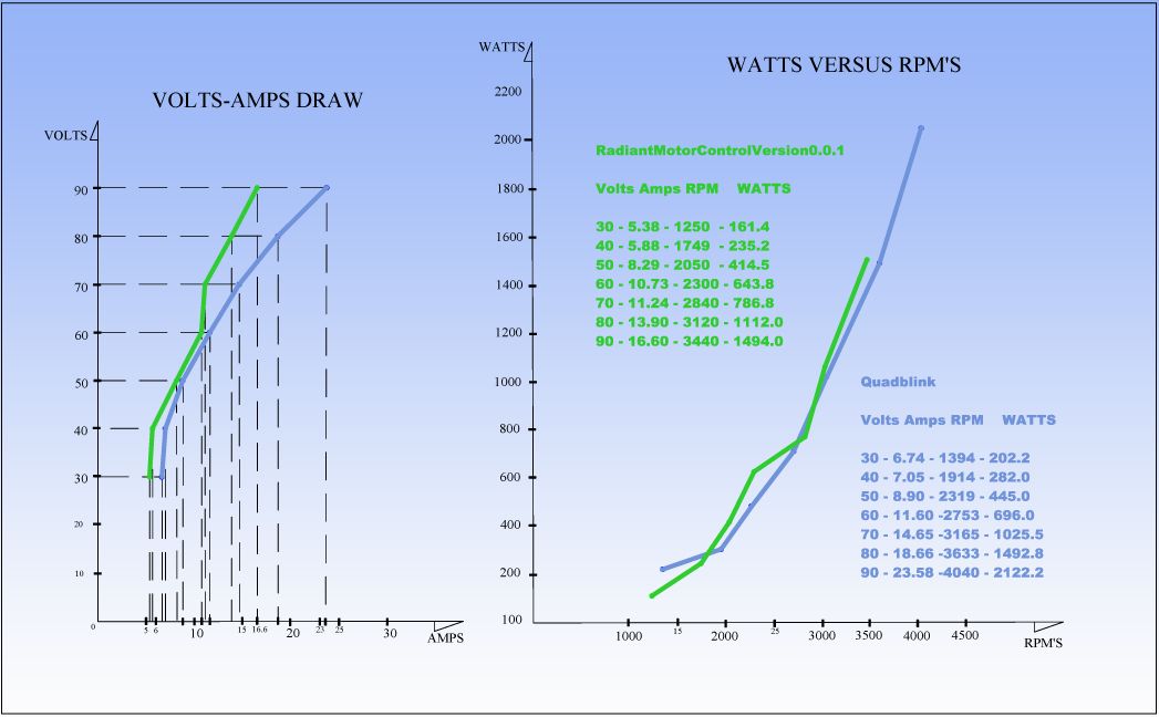 [/IMG]
I made this Flow Chart according to Hitby Data...
When we see both curves at both charts...we see almost same Issue...
GChilders Radiant Motor Control needs to be "Stretched Out" ...to obtain a similar or even better "smooth" flow result, as Quad Blink does....and that eventually will create same effect on amplifying Speed/Reducing Amp Draw...
If You notice the "Area of Conflict" comprehend same close points...
Create the "Ideal Flow Curve" (I will do it tomorrow...forgot to, and is too late) to be Your Guide to approach...
And really...looking at RPM's reaching range required for Generator Head, or 3600 [look at 80 Volt Feed for both Systems]......we notice that Gerry's is only behind by 480 RPM's...which is not much...
Now, Gerry's Codes have much more Parameters to "Play" with, therefore, is more complicated to Set Up...but am sure as you get the "Name of the Game"...it will be an "Easy Piece" to Adjust...
At the same token...the fact of having more parameters...basically fragmenting/dividing the On Times (Duty), creates this starting situations...
Quad Blink have just one Big "On Time" Pulse...reason why it could turn Motor at lower voltages...(2.0 Volts)
Gerry's have same On Time but divided through Time into smaller pulses/On Times...so the "juices" that reach every Coil per same unit of time is Too Small to move Coils...like I wrote before...not enough time for a strong magnetic field to develop.
But am very sure everything could be worked out and be very, very efficient.
If You could see the "MAX DRIVE" for a Motor...would notice that, if we make even more number of Gates/Brushes...and increase Voltage...Amps would be reduced even more...Now, Gerry's codes are doing just that without going into structural changes...
An "Ideal" Pulse Sequence would be to start with stronger magnetic fields on the core, Filling those coils with longer On Times...till reaching a steady RPM's/Breaking Inertia Forces....then start fragmenting it for shorter times On...and Higher Voltages...rendering much less Amp draw...This is the Basic Game here Guys...
You guys are doing a Beautiful Work!!...Awesome...and extremely interesting!
Kind regards to all
UfopoliticsLast edited by Ufopolitics; 07-26-2013, 07:14 AM.Leave a comment:
-
rmc timing
@all
I noticed that both Dana and Hitby13kw have attempted to use the timing commands. This is an idea that I was working on but has absolutely no effect on the motor as there is no connection in code other than to echo back that the timing has changed. No effect at all. It was an oversight on my part to leave those commands there. Sorry for the illusion that timing had been worked into the program. Ignore those commands they have no effect.
Every one seems to be very excited and changing things in the program. Hopefully you fully understand how the program works before you make changes. It can be dangerous to you and your machinery if you do not. There are many interrelated pieces and a change in one area can effect changes in other areas. Just a word of caution. Make sure that you truly understand the ramifications of your changes before making them. Please copy and paste the changes that you make in a pm to me so that I can verify that the changes that you made are solving the problem or are creating the problem.
@hitby
it seems that your rpms are extremely low. when you say that you made the changes that I talked to Dana about could you please be more specific than that, please copy all code that you have changed after changing it and paste it into a pm to me so that I can verify that the changes are correctly done and are not going to affect a part of the code that you were not aware of. I would prefer that. I do not want to be a buzz kill or for you to think that you are incapable of making changes but at this point I do not know the coding skills of the individuals in the forum very well and it takes a while to fully comprehend the code, especially if you are at a fairly basic skill level. I trust that you will not be offended by this but I have your safety in mind.
below are the only changes Dana and I have discussed
void loop() {
//have the arduino wait until it receives a message
if (Serial.available() > 0){
// Read serial input
while(Serial.available() > 0){
msg += char(Serial.read());
delay(250); change this to 25 milliseconds and see if the problem is solved. The problem may manifest it self in the serial monitor echo being broken instead of echoing the command. in other words motor started will break up into different lines. we changed this to 15 milliseconds instead of 25
a little further down there is this line in the serial commands
else if (msg == "Start"){
boolianMotorSpeedRamp = 1;
motorSpeedRamp(0, 65); what do you have here, copy and paste please?
Serial.println("Motor Started");
}
This is the most critical area to change for smooth start ups and I have yet to get a single piece of solid feed back from any on what they have done in this area please give me this information words only cloud the issue if they are not framed in the right context.
Thank you for all the kind words and accolades but there is a lot of work to be done and this will speed things along.
you should have raised the 65 to new number and rechecked the rpms if you have not then please raise it to 90 and do another run to see if the rpms have come up to where they need to be. We need to trim the motor speed now while it is not under load that is step one people get the rpms up to 3600 plus anything less is unacceptable.
cheers,
GarryLeave a comment:


Leave a comment: