Announcement

Collapse
No announcement yet.

My Motors got me to Tap into Radiant Energy

Collapse
X
 
  • Filter
  • Time
  • Show
Clear All
new posts

  • Cornboy 555
    replied
    Driver section.

    Hello JS, everyone, have finished the driver section of the Monster, man it's good to see that led flash to your pulse input.

    You are a very good teacher JS, i feel confident enough, to even trouble shoot a problem now, Thanks so much.

    I have a scope that goes to 2.5ns/div but am still trying to work out how to use it, but all looks good with the monster so far.

    [IMG][/IMG]

    Warm Regards, Cornboy.

    Leave a comment:


  • Hitby13kw
    replied
    temperature sensors

    @ Team & John Stone, Been looking at other temperature sensors that are available, came across the DHT11 and his big brother the DHT22 this sensor can also report the humidity and dew point data, and you only need one digital pin for each sensor so multiple data points (both bearings, each of the eight brushes, the motor case, etc.) would be a piece of cake, main downside is this unit is slow ~ can only pull data from it once every 2 seconds.

    Another unit that might be worth considering is the DS18B20 it is offered in two versions, just the sensor and in a nice protective case with 3 foot of wire either way, this unit communicates via

    Hitby13kw

    still working the plan

    Leave a comment:


  • Cornboy 555
    replied
    Pics

    Originally posted by GChilders View Post
    @John Stone
    Hi John,

    When I finished the third replication I cut a four inch diameter piece of lexan and two 2 inch diameter pieces to reinforce this piece. I then drilled 4 mm holes in the center and epoxied a 1 inch diameter 3/8 inch thick piece of aluminum, that had been drilled and tapped with a set screw , with this assembly. This is what I am going to use for two purposes. First this will act as the timing mechanism for the motor, and secondly as a tachometer. How will I accomplish this dual purpose. First my choice as I had mentioned before in the forum before I wrote the tiny piece of code that was used to demonstrate the quad fade method. I have chosen to use an infrared transmitter coupled with an infrared receiver which is coupled to the interrupt signal of the Arduino. These are dirt cheap, they are everywhere and ultra dependable. They are used here in the US for safety of garage door closers. The one that I have on my garage door has been faithfully operating without a hitch for over twenty years. The lexan wheel can be manipulated in two ways, in order to adjust the coarse and fine tuning of the motor. First I set the coarse tuning with the set screw, I can change this at any time when the motor is stopped, advance or retard the timing easily. Second, by using any opaque tape I can incrementally change the timing until a sweet spot is found. By moving the motor control code into the interrupt sub process this can be used to time the motor in a very satisfactory way as the code will be executed every rotation of the motor and all adjustments to the duty cycle and such will be calculated upon every revolution of the motor since the interrupt in this instance will only occur once per revolution. Any way that is my solution which may not work for some applications. Hope that it helps.

    Cheers,

    Garry


    Hello Garry, thanks once again for joining in like you have, it would be a great help to all here if you could perhaps, include some pics of what you are doing, to give us a clearer understanding.
    Thanks once again,

    Regards Cornboy.

    Leave a comment:


  • JohnStone
    replied
    Originally posted by GChilders View Post
    @John Stone
    Hi John,

    When I finished the third replication I cut a four inch diameter piece of lexan and two 2 inch diameter pieces to reinforce this piece. I then drilled 4 mm holes in the center and epoxied a 1 inch diameter 3/8 inch thick piece of aluminum, that had been drilled and tapped with a set screw , with this assembly. This is what I am going to use for two purposes. First this will act as the timing mechanism for the motor, and secondly as a tachometer. How will I accomplish this dual purpose. First my choice as I had mentioned before in the forum before I wrote the tiny piece of code that was used to demonstrate the quad fade method. I have chosen to use an infrared transmitter coupled with an infrared receiver which is coupled to the interrupt signal of the Arduino. These are dirt cheap, they are everywhere and ultra dependable. They are used here in the US for safety of garage door closers. The one that I have on my garage door has been faithfully operating without a hitch for over twenty years. The lexan wheel can be manipulated in two ways, in order to adjust the coarse and fine tuning of the motor. First I set the coarse tuning with the set screw, I can change this at any time when the motor is stopped, advance or retard the timing easily. Second, by using any opaque tape I can incrementally change the timing until a sweet spot is found. By moving the motor control code into the interrupt sub process this can be used to time the motor in a very satisfactory way as the code will be executed every rotation of the motor and all adjustments to the duty cycle and such will be calculated upon every revolution of the motor since the interrupt in this instance will only occur once per revolution. Any way that is my solution which may not work for some applications. Hope that it helps.

    Cheers,

    Garry
    Hi Garry,
    I pondered on this item for long time in order to find a general solution easy to use and I decided that it depends essentially on individual setup. Now our community has the choice from very different approaches and everybody will decide for his preference.
    I understand you have a vane wheel and a photo interruptor. Your vane has as many slots as your armature poles. That is exactly what Cornboy plans to do.
    I am a visually oriented person and my imagination might be wrong. I still ponder on how you know which driver to operate at which interrupt. I can imagine to either have 4 (6 for Cornboy) sensors or a trick to synchronise full revolution. Would you mind to post a pic of your suggestion?

    But I have an additional question:
    If we have an interrupt for every pole passing - and given this interrupt occures in advance of pulse start intended. Will it be possible to retard the pulse by program in steps of i.e. degree. This feature would ease massively finding sweetspots without any mechanic provisions.
    We know timed distance of vane interrupts and we know how many degrees they represent. This will suffice to get electronic ignition timing run. Just an idea!
    John

    Leave a comment:


  • JohnStone
    replied
    Instructabel E: FET driver

    Hi Cornboy and sthose builder of moster drivers in obscure!
    Congratulationss! Now you have successfully built the environment where the true FET driver will dwell happily. It lives like queen bee in a hive.

    Now lets look at those inhabitants: FET driver, FETs and protection circuit. In this session we will deal with FET driver only.
    But first of all I want to explain why we need a dedicated FET driver while others can drive some FETs from Arduino directly or by a simple NE555 timer circuit or other small bore components. All is a matter of performance.very short time in intermediate state of half open / half close - an extreme lossy state. Apart that we foster radiant if we get switches go as fast as possible.
    All facts above relate to switch off state as well.
    Just as short hint: The other capacitance Cgd is a penetrant antagonist to our FET driver. I do not want to go in detail but please understand that if we want to make the FET conductive it will oppone. If we want to get current flow shut - it will oppone...... So understand the driver is loaded with this fight as well and it will get more seriously if we deal with increased voltage in our setup.
    (BTW: A FET is theoretically infinitely fast (some picoseconds). Only those capacitances are responisble for slowness. Silicon Carbide (SiC) technology allowes much less capacitance and hence those components can switch much faster ... and they purge your purse much much faster than you can watch - currently)
    Now you possibly understood the right to exist for this tiny FET driver. And you hopefully understand that this team is well tuned. Any modification neds to regard all seide effects mentioned above and some more I will not dicuss here.

    Resistor R8 stays there in order to get input securely low at power on time. We do not want any unsolicited switching action while power on state.
    The driver requests a steep edge at input signal in order to prevent unsolicited spuirous spikes at output. Therefore we conditioned the signal with the logic IC from last section.
    And last but not least we have a LED at output in order to have a visual feedback of operation. (R7, D11)

    Now, assemble components mentioned above and and play with your circuit. Operate input manually or by a generator and observe behaviour of LED. It shall be on or off but not glowing with half intensity.
    For first PCB it is advisable to use an IC socket for IC7 but for the other boards please omit it. We do not want to add additional drawbacks for our dream team.
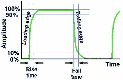
    If you have a scope please measure the signal at IC7 pin 1 and pin 3. You should not have any spurious oscillations or lazy edges in your signal measured. For reference please note the time the signal goes from low to high (rise time) and vice versa (fall time). You will recheck this measurement after adding your FETs in next section F.
    BTW: rise and fall time of signals regards the time from 10% to 90% of high signal amplitude.


    BTW: Your seemingly fast scope might be too slow in order to see any slope. The time expected will be far below 50ns!!!!!

    Check operation with sine or trinagle signal from your generator. The slopes shall be of same quality like at square wave. You possibly will observe change in duty cycle. Do not mind it.

    Apply a signal with low duty cycle and observe the output of driver. Is it same or inverse? Memorize it! Later on you might want to know at what input signal FETs are on or off.

    You might feel that a seemingly delicate circuit is very easy to build. You are right - thanks to those scientist who invented integrated circuits and sophisticated this technology constantly. Thanks to them we have today cheap Arduinos in private use and monster drivers with performance not being imaginable some years ago. So please regard this success of global community as well. On the other hand we intend to add with these tools another realm of new knowledge to energy processing.

    JS
    Last edited by JohnStone; 08-27-2013, 08:05 PM.

    Leave a comment:


  • GChilders
    replied
    RPM Sensor

    @John Stone
    Hi John,

    When I finished the third replication I cut a four inch diameter piece of lexan and two 2 inch diameter pieces to reinforce this piece. I then drilled 4 mm holes in the center and epoxied a 1 inch diameter 3/8 inch thick piece of aluminum, that had been drilled and tapped with a set screw , with this assembly. This is what I am going to use for two purposes. First this will act as the timing mechanism for the motor, and secondly as a tachometer. How will I accomplish this dual purpose. First my choice as I had mentioned before in the forum before I wrote the tiny piece of code that was used to demonstrate the quad fade method. I have chosen to use an infrared transmitter coupled with an infrared receiver which is coupled to the interrupt signal of the Arduino. These are dirt cheap, they are everywhere and ultra dependable. They are used here in the US for safety of garage door closers. The one that I have on my garage door has been faithfully operating without a hitch for over twenty years. The lexan wheel can be manipulated in two ways, in order to adjust the coarse and fine tuning of the motor. First I set the coarse tuning with the set screw, I can change this at any time when the motor is stopped, advance or retard the timing easily. Second, by using any opaque tape I can incrementally change the timing until a sweet spot is found. By moving the motor control code into the interrupt sub process this can be used to time the motor in a very satisfactory way as the code will be executed every rotation of the motor and all adjustments to the duty cycle and such will be calculated upon every revolution of the motor since the interrupt in this instance will only occur once per revolution. Any way that is my solution which may not work for some applications. Hope that it helps.

    Cheers,

    Garry

    Leave a comment:


  • Cornboy 555
    replied
    Bugger.

    Hello John Stone, Et al, have finished and tested nand gate section, of Monster, i am sorry for taking so long, for some reason i wasn't expecting the very next post to be the next instructable, and i missed it.

    So i was waiting for John to post it, thinking he's busy, then going back, i found it, and was very embarresed.

    Thanks John, ready when you are!,

    Warmest regards, Cornboy.

    Leave a comment:


  • RAMSET
    replied
    Gentlemen, a formal invitation

    A chance to teach and be taught ,a chance to showcase and experiment.

    But most of all some good clean fun.....

    Here

    Welcome To The 2013 Pulse Motor Build Off!! Ready Set GO!!! Its ON!! - YouTube

    Direct link to the forum
    International Alternative Energy Center - 2013 Pulse motor build off - Powered by ForumCo.com - The Forum Company

    Thx
    Chet
    PS
    Girls are allowed too.......................
    Last edited by RAMSET; 08-26-2013, 01:35 PM.

    Leave a comment:


  • machinealive
    replied
    Good-day

    It took a while but I managed to get boxes finished, and sensors setup. It's funny you bring up rpm Johnstone, because for some reason, that was the only a sensor that didn't record right. Reading was quite a bit higher then measured, and slowly increasing. Current sensor seemed good, at 12 v, the current measured b/t 10 and 11 amps, as measured initially, with DMM. So, I'll be looking at the rpm program today.

    Machine

    Leave a comment:


  • iankoglin
    replied
    Originally posted by Zardox View Post
    Thanks Kogs for the nice clear photos of your driver. I finally have some of the parts ordered to get started and that will be a big help.
    G'day Zardox
    Thanks for the commendation I used my IPad it takes great photos
    The Monsters are the exact ones that John Stone designed with the exception I have widened the gap between C7 and the Mosfets this allows me to put the R7 on top and makes it easier to solder the Mosfets also the lands are slightly wider than John Stone had made to allow more solder as he suggested.
    I used "Fab in a box to make the PC Boards.They come out all right

    Kindest Regards


    Kogs still here

    Leave a comment:


  • Zardox
    replied
    Thanks Kogs for the nice clear photos of your driver. I finally have some of the parts ordered to get started and that will be a big help.

    Leave a comment:


  • JohnStone
    replied
    RPM sensor

    Hi guys out there
    still pondering on rpm sensor and how to intergrate it.
    What about tachogenerator out from washing machine motors (source = junk yard). They have a magnet ring around the shaft rotating and a pickup coil around it not moving.
    Diametrical magnetisation (2) of magnet required! (not like speaker magnets (1)!)
    • 1) axial magnetisation
    • 2) diametrical magnetisation
    • 3) radial magnetisation

    Example for source and here .
    Transistor and resistor required to adapt to Arduino interrupt. The magnet ring can be glued or screwed to end of shaft if diameter does not fit.
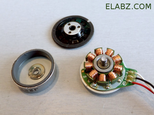
    I have no such motor available and do not know how many pulses they emit per turn. Can somebody check how those tacho sensors perform?


    Similar procedure if you add a drive motor from CD/DVD device.


    JS
    Last edited by JohnStone; 08-26-2013, 12:45 PM.

    Leave a comment:


  • Midaztouch
    replied
    Great!

    Originally posted by iankoglin View Post
    G'day Team

    of the 2 monster driver I made the first worked OK the second ? I need to diagnose it
    As I said I would post some pics of my progress so here they are

    Kogs UFO Projects Photos by Kogs1 | Photobucket

    I had trouble getting my test driver mobile as she had not ridden a bike for quite some time I'm sure she will feel safer when she test Drives EVTrike1


    The motor is a standard MY1018 36v 250w motor
    I now have to keep using Kogs EVbike1 to see what problems I may encounter then I will exchange the motor with a Asymmetrically wound motor ( I have to buy 2 more motors to do this).

    In the meantime I will be Wiring my 1000w Chinese motor to fit in my EVTrike1 of which I will use firstly the same set up then use an Arduino to control the motor to see what the difference is.

    Kindest regards to you all


    Kogs still progressing trying to catch up, running out of time
    Kogs,

    Awesome! I loved the smile on your wife's face. That's what we call an EV Grin.


    When you use your Asymmetric motor, there shouldn't be any overheating with your boards. Also use a chain from the motor to the gears. If you want to reduce the size of the box on the back by 1/2, buy lipo batteries. Anything over a 20c rating will not be dangerous for your 1000w motor. Your max amp draw will be less that 25% of the batts max amp discharge.
    Hobbyking has a lot of choices.
    ZIPPY Flightmax 8000mAh 6S1P 30C


    Keep it Clean and Green
    Midaz
    Last edited by Midaztouch; 08-26-2013, 06:18 AM.

    Leave a comment:


  • iankoglin
    replied
    Kogs EBike update

    Originally posted by iankoglin View Post
    G"Day Team
    Thursday I finished building another 2 John Stone's Monsters (untested) also modified my Oscillator to accept the 5k ohms twist throttle. Yesterday I received 3 - 7.1ah SLAB's. Today I finished rehashing my box to fit all the components in and enough room to fit 3 more batteries if I want to. I connected all the components ( including another Motor not connected to my Bike) and connected the batteries every thing went sweet. Tomorrow or Monday I will finish connecting everything permanently and take some pics.

    G'day Team

    of the 2 monster driver I made the first worked OK the second ? I need to diagnose it
    As I said I would post some pics of my progress so here they are

    Kogs UFO Projects Photos by Kogs1 | Photobucket

    I had trouble getting my test driver mobile as she had not ridden a bike for quite some time I'm sure she will feel safer when she test Drives EVTrike1


    The motor is a standard MY1018 36v 250w motor
    I now have to keep using Kogs EVbike1 to see what problems I may encounter then I will exchange the motor with a Asymmetrically wound motor ( I have to buy 2 more motors to do this).

    In the meantime I will be Wiring my 1000w Chinese motor to fit in my EVTrike1 of which I will use firstly the same set up then use an Arduino to control the motor to see what the difference is.

    Kindest regards to you all


    Kogs still progressing trying to catch up, running out of time

    Leave a comment:


  • Cornboy 555
    replied
    That looks Great Machine, i will build something similar, probably 120mm square, to house my final 9 monsters, with a 120mm fan on one end, or both if needed.

    Good Work, Cornboy.

    Leave a comment:

Working...
X