Announcement

Collapse
No announcement yet.

My Motors got me to Tap into Radiant Energy

Collapse
X
 
  • Filter
  • Time
  • Show
Clear All
new posts

  • Ufopolitics
    replied
    About HER...

    Originally posted by Cornboy 555 View Post
    Hi DANA, i am getting C2D10120A, 1200v 25A, you could use them across the fets, for extra protection, i am using them for radiant experiments, now that i have a reliable pulser.

    I have three neons across outlet on pulser and have already tried 50 Ns diodes, as soon as you introduce a path for her majisty, the neons won't light, i am hoping with the Sic diodes with no reverse time, they will let here out, with more amperage, before she increases so far in voltage.

    I will do a proper set up and vid it for all.

    Regards Cornboy.
    Hello Cornboy,

    One small advice...

    Whenever you allow a Path for "Her Majesty"...please do not do it at High Pulses/High Frequency...or High Duty...or else SHE will keep blowing any neon's you connect in Her path.

    Try very low pulses first, meaning from 4-8 Hertz...9 MAX...then you will see Her purple light (plasma ball) on Neons...but you will also see some orange (Hot) Light, but at those low pulses SHE will prevail...Hot would be weak.

    Neon's can not afford the presence of both Energies at higher pulses...

    Just some hints to have some fun.


    Warm regards


    Ufopolitics
    Leave a comment:


  • Cornboy 555
    replied
    Originally posted by prochiro View Post
    Cornboy


    Are those diodes for the mosfet or what. If for fet, I wonder what diode you have selected as I am having trouble selecting a diode with enough voltage. As for other Cree products, the CREE SiC-FETs from are 47.00 dollars but that just may be the cost of making things go fast.
    Dana


    Hi DANA, i am getting C2D10120A, 1200v 25A, you could use them across the fets, for extra protection, i am using them for radiant experiments, now that i have a reliable pulser.

    I have three neons across outlet on pulser and have already tried 50 Ns diodes, as soon as you introduce a path for her majisty, the neons won't light, i am hoping with the Sic diodes with no reverse time, they will let here out, with more amperage, before she increases so far in voltage.

    I will do a proper set up and vid it for all.

    Regards Cornboy.

    Leave a comment:


  • prochiro
    replied
    Cornboy

    Still waiting for Cree SiC diodes
    Are those diodes for the mosfet or what. If for fet, I wonder what diode you have selected as I am having trouble selecting a diode with enough voltage. As for other Cree products, the CREE SiC-FETs from are 47.00 dollars but that just may be the cost of making things go fast.
    Dana

    Leave a comment:


  • JohnStone
    replied
    @UFO: In terms of conventional electronics those resistors will not get overloead unless we pulse them in MHz ramge. There is not parasitic component in the FET being able to deliver such current without damage of FET.
    But you are completely right: radiant pefroms conforming additional physics and migh thave a secret tunnel through FETs.
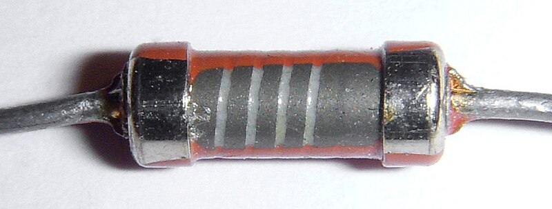
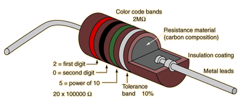
    As tradeoff I suggest to add several resistors in parallel i.e. 5 x 100Ohm or what you have in your scrab box. But please use metal film or carbon composit resitors. Standard carbon film ones have acarbon coating and for value adjustemnt they mill a spiral around. This shape IS in fact a COIL as well and might foster oscillations.

    Carbon composition:
    [IMG]

    Carbon film (inductive):


    Reviewing current production technology for metal film resitors I detected that some manufactureres use helical trim as well.

    But if we decide to stack those resistors we can use SMT types (recommendation: size 1206).

    Those have surely minimal inductance possible.


    @Garry: Sorrry for not specifying exact types of xx7805xx. The advice you got from others is correct. Nothing to add.

    @Cornboy: Congratulations: You can be proud of you! Very well manufactured. We pomized you to get here to - is it? I hope others working in obscure are as successful.
    You might buy a bunch of 100Ohm 1206 resitors and try to get rid of those 1.7 MHz oscillations. Those resistors cost allmost nothing.
    JS

    Leave a comment:


  • Cornboy 555
    replied
    Monster In The House.

    Hello all, it's alive and Kickin', my first Monster, and i mean kickin, dont touch the heatsink when you are pulsing a coil without diodes fitted to take away the lady!!

    The three neons were lighting at 2HZ with 12V, pulsing a coil of 2.4 ohm 1mm wire, so i didn't push it any further.

    Still waiting for Cree SiC diodes, then i will make a small vid of some experiments, i've been wanting to do, finally with a pulser that's designed Strong.

    Thanks JS, and Sampojo.

    I installed Fets on top side and heavy wiring and gate resistors, on bottom, trying to get as compact and thin as possible, will be mounting 9 of these in an aluminium case with fan.

    [IMG][/IMG]

    [IMG][/IMG]

    [IMG][/IMG]

    @ JS, nice square wave at gate, with no resistors, and at 2.5Ns on scope showed around 1.7 Mhz ocillation, in the shape of a sine wave, so i fitted 4 ohm resistors, and still same ocillation.

    Slow pulsing a coil, at 2hz, nothing showed the slightest sine of any heat. went up to 13Khz, with light bulb 12v, no heat anywhere.

    Have to go make a livin, packing eggs today.

    Warm Regards Cornboy.

    Leave a comment:


  • prochiro
    replied
    Garry
    Typically. the 7805 series carry a current from 1 to 1.5 amps. For practical purposes, they can be considered the same for most cases. Some are labeled "L", "LM", and some just a 7805. The letters after the number are a little more important but not really for us. If you want a 7805 and 7812 just look for those numbers and order some. I use what is called L7805cv.

    Now if you are ordering diodes for the monster, that is different. We then find that the name of those diodes has many sub types that are selected by just what we want the diode to do or withstand. If your fet type changes, so does the diode type.
    Dana

    Leave a comment:


  • GChilders
    replied
    Pics

    @Cornboy, Dana

    Thanks for the info on pics. I thought it was something like that. Anyway I will open a photobucket account.

    @ John Stone

    John I couldn't find a voltage regulator 7805, or 7812 will the LM7805CT, and LM7812CT by Fairchild work ok.

    Thanks Garry

    Leave a comment:


  • machinealive
    replied
    If the driver can source 12amps briefly, at 12 v. That's 144 watts. That is why resistors are frying? I didn't lose any fets, on new board, just resistors. So 12v/20ohm is only 600 ma. I never had a chance to try the 20 ohms yet, until i finish with the hgs, but I'm sure they would be fine. I still wonder how Dana is getting away with using 1 ohm.

    Leave a comment:


  • Ufopolitics
    replied
    Just a Thought...

    Originally posted by JohnStone View Post
    Hi Dana,
    there are several possible deseases we need to cure. AS I still wait for my PCDs it is a kind of blind flight for me - and unfortunately for you.
    FETs can break down because of too hihg voltage but they suffer on too fast voltage increase as well. Then they might break down at lower voltage than specified.
    Sorry for being superficious at last paragraph at my yesterday post. It was late night.

    A: Using neons is the first cheap approach for curing overvoltage and adds the advantage that you can see if they are active and perform their dedication. Fortunately neons are quite fast as well.

    B: Any FET has an intrinsic parasitic diode because of semiconductor process. This diode protects the FET from reverse voltage by shorting D/S in this case but for reverse voltage only - of course. This case occures if we drive a coil / motor and at switch off it starts oscillating with its natural frequency. Now tehre are cases wher the negative voltage occures instantly and increases to dangerous values BEFORE this intrinsic diode awakes from snoozing. Because auf manufacturing process of FETs it can not bemade fast er. In these cases we add an exrernal fast diode in order to act in right time omitting nay action of the intrinsic diode.
    1N914 is fast but 100V only. It will die instantly if spikes go well above 100V . But together with one single neon it might do well. Just now I have no recommendation because there are thousends of types available. You may ask here for types you have available. I will consult for you data sheet.

    C: The snubber components can be added in order to slow down excessive steep voltage increase (steepness of edges) and protect FET form lower voltage breakdown. They consume the energy for short time and make edges less steep.

    All of those measures degrade switching capability a bit. Therefore they shall be added if required only. Those cases depend strongly on individual setup (L of motor, current, voltage .....).
    As the reports state that gate resitors die I assume a voltge breakdown from drain to gate. Is there any knowledge what components die aside gate resistors. Such info might give some hints to real cause of problem.

    JS

    Hello John Stone, Hello All,

    I was thinking (and it is just a "fast" thought)...I highly could be very wrong...

    Could we add Higher Wattage resistors at Gates?

    It seems like the FET's are allowing certain HV flow back through their Semi-Conducting Internal composition from Drain to Gate...and they do not blow simply because their High Voltage rating (600V)...(also have in mind the speed and Capacity of Radiant Energy...SHE will make paths where there are none) but burning resistors from a "backend flow"...as I have not heard that the component before resistors gets damaged....which I believe is the opto?

    Is just a thought.


    Warm regards


    Ufopolitics

    Leave a comment:


  • JohnStone
    replied
    Hi Dana,
    there are several possible deseases we need to cure. AS I still wait for my PCDs it is a kind of blind flight for me - and unfortunately for you.
    FETs can break down because of too hihg voltage but they suffer on too fast voltage increase as well. Then they might break down at lower voltage than specified.
    Sorry for being superficious at last paragraph at my yesterday post. It was late night.

    A: Using neons is the first cheap approach for curing overvoltage and adds the advantage that you can see if they are active and perform their dedication. Fortunately neons are quite fast as well.

    B: Any FET has an intrinsic parasitic diode because of semiconductor process. This diode protects the FET from reverse voltage by shorting D/S in this case but for reverse voltage only - of course. This case occures if we drive a coil / motor and at switch off it starts oscillating with its natural frequency. Now tehre are cases wher the negative voltage occures instantly and increases to dangerous values BEFORE this intrinsic diode awakes from snoozing. Because auf manufacturing process of FETs it can not bemade fast er. In these cases we add an exrernal fast diode in order to act in right time omitting nay action of the intrinsic diode.
    1N914 is fast but 100V only. It will die instantly if spikes go well above 100V . But together with one single neon it might do well. Just now I have no recommendation because there are thousends of types available. You may ask here for types you have available. I will consult for you data sheet.

    C: The snubber components can be added in order to slow down excessive steep voltage increase (steepness of edges) and protect FET form lower voltage breakdown. They consume the energy for short time and make edges less steep.

    All of those measures degrade switching capability a bit. Therefore they shall be added if required only. Those cases depend strongly on individual setup (L of motor, current, voltage .....).
    As the reports state that gate resitors die I assume a voltge breakdown from drain to gate. Is there any knowledge what components die aside gate resistors. Such info might give some hints to real cause of problem.

    JS

    Leave a comment:


  • prochiro
    replied
    Originally posted by
    [COLOR=Red
    I urge you to add some additional protection components:[/COLOR]
    A: Add a neon in parallel to FET pin 2, 3. It will light above 90V. Check with motor under load if it lights. If yes replace neon by two or three of them in series.
    B: Add a fast diode in parallel to FET pin 2,3. There are operating conditions where the internal parasitic diode is not fast enough in order to protect from reverse polarity when inductive loads are being switched off.
    C: You might want to add a so called snubber circuit in parallel to above circuts: Resistor 68 Ohm and cap 390pf 500V in series.
    @JS
    Just to make sure I am thinking correctly, on item B, the diode is from pin 3 to 2 , correct. Would a 1N914 or be enough? I also see on some diagrams both item A and B inserted. Good or bad here: I am doing fast and high revving tests from 12V to ?
    Dana

    Leave a comment:


  • Cornboy 555
    replied
    Hey John Stone, thanks for final instructable, very much appreciated, will try to get it completed tonight, and scope final output, to post here.

    Thanks Again Friend Cornboy.

    Leave a comment:


  • Cornboy 555
    replied
    Hello Garry, like DANA says, open a free account with photobucket, then upload your images, to there. when images are at photobucket, go to your library, put cusser on photo you wish to share, and click share, then click on top RH -- links, then click on IMG codes, it will go coloured, yellow i think, that will copy photo.

    I always start my post first, then transfer photo, to post on forum, you click on small yellow square, which says insert image, a box comes up, then right click on blank box and choose paste, and then ok.

    Hope i havn't confused you any.

    Please keep asking if un clear.

    Regards Cornboy.

    Leave a comment:


  • prochiro
    replied
    Hello Garry
    If I am correct, Dropbox only gets you the link which is OK but not showing on your screen. Photobucket loads the picture into the page.
    Cant wait to see the new version.
    Dana

    Leave a comment:


  • JohnStone
    replied
    Instructabel F: - Monster Driver

    Today we focus on final part F -the real power unit.
    We have two FETs in parallel in order to achieve safe current switching of about 100A. If this is oversized for your application please assemble only one FET along its associated componets. In fact I ask all of you to do it first in order to get clear test conditions. OK - let's focus on T1 and componetns around.

    These FETs of N-type will conduct current if we switch voltage to gate (T1 pin1) referenced to source pin (T1 pin 3)
    BTW: Why pin 3 is source while it is connected to battery GND? There is a damn simple answer. Our battery sources electrons at GND lead!! The real physical current flow is from GND to +. Based on historical facts we think in terms of so called "technical" current flow - reversed to reality. In fact old Japanese transistor circuits were drawn conforming physical current flow but nowbody abroad could read them. Later on they adapted the technical current flow.

    You have successfully tested your FET driver and now you can be confident voltage WILL be switched to gate.

    Pulldown resistors R5 / R6 are there for safety reasons. The FET shall be safely switched off if we have any interruption to FET driver. Gate insulation to source (pin3) and drain (pin2) is in range of gigaOhm that is more than some caps or PCB might have. Therefore we can not prevent some single electrons to escape to gate crowding there and eventually making the FET conductive.

    Now let's look at those strange 1Ohm resistors. They serve for safety as well - minimizing unsolicited oscillatons in driver circuit.

    Facts: A FET is much more faster in switching than the data sheet tells us. I talked of this tiem in last instructable. A FET is a circuti in itself and contains many unwanted (parasitic) but real capacitances. This is a side effect of semiconductor structures. If we control a FET intent ionally we need to charge and dicharge those internal caps - that takes time and makes the FET slow in swiching properties.
    But there are cases where those caps enter a spurious oscillation. The traces to gate and gate pin itself are in fact minute inductances and together with internal gate cap they build up a nice tank circuit. While oscillating the FETis being switched rapidly along oscillations at every edge of switch action intended.

    .
    In case of oscillations apart from minor signal quality our FETs will suffer from heat problems. At every edge it sweeps over a range of mid resistance but increasing current (P = I*R^2).
    You will not get these oscillations for sure but you never know when and where they occure. You might suffer of premature FET death.
    As you know we can counteract oscillations with resistance. This is true in mechanic matter and electric as well.


    Here R3, R9 come into play. They need to be tuned to be as low as possible and as high as to dampen oscillations. The value 1R is a place holder only. Some circuits need 5 Ohm others up to 47 Ohm. It can't be predicted.
    If you have no scope please use 22 Ohm or 33 Ohm and check for heat later on.
    If you own a scope you will start with 0Ohm (simple wire) and check for oscillations. Then you increase up to the state where you have no oscillations left. You will perform this test with resistive load i.e. a car headlamp connected to 12V. (see procedure below)

    Our FETs are still vulnerable. Excessive voltage spike above 500V might destroy it by voltage breakdown. When driving inducive loads like motors this case can occure easily even at small motors. In order to prevent this danger you find D5, D8 (D9, D4) there in teh circuit diagram. They will break down above about 450V and add voltage to the gate - and as we know it will reopen and short circuit this spike to GND. After that (killing the spike) it will interrupt current as requested.
    But the gate is not allowed to get more voltage than 20V. In order to prevent this danger we have added D1 and D2 and C9 (D6, D7, C15). These components will short circuit any voltage higher than 15V. I do not want to dig in the details on why this last protection circuit is as it is in order to not deviate from goal.

    Hands on:
    1. Assemble T1 and components around (leave T2 for now). You may want to assemble provisionally the FET an top of PCB but please double check correct pin arrangement and solder the FET on long legs with few solder.

    2. Connect a car bulb (21W direction indicator) first to 12V as load. Operate your generator and measure driver output, gate of FET and voltage at load for correct funktion. Check the load to get switched on if you activate your circuit and observe FET pin 2 to go low.

    3. Check for oscillations at gate. Now is the time to tune gate resistors like described above. You might want to approach from high OHM i.e. 33 Ohm and later on adding another in parallel up to the occurance of oscillations.
    Replace bunch of gate resistors by a single one with corresponding value.

    If you have no oscillations at all, solder about 5 or 10 Ohm as gate resistor.

    Check with higher frequency i.e. up to 10KHz or more. Play with duty cycle.

    4. Add car headlamp (H4 or several H7...) as load - single filament / both filaments in parallel and check function and for oscillations like above.

    5. Play with frequency and duty cycle and measure in your circuit in order to get aquainted with its behaviour. For your memory find the areas where the signal is being inverted in polarity regarding oscillator input.

    6. Now you may add the second circuit around T2. Disconnect R3 from T1 in order to inactivate it and procede like above with T1.

    7. Reconnect R3 for full function.

    Congratulations! You're done!


    HINT: Some of you still suffer on dying components like FETs and gate resistors. (How do yu kill 1Ohm rsistors????? )
    I apologize for this flaw still being present and up to now I have no idea what the reason is. I will investigate ist as soon I get my PCBs from Oshpark.
    I urge you to add some additional protection components:
    A: Add a neon in parallel to FET pin 2, 3. It will light above 90V. Check with motor under load if it lights. If yes replace neon by two or three of them in series.
    B: Add a fast diode in parallel to FET pin 2,3. There are operating conditions where the internal parasitic diode is not fast enough in order to protect from reverse polarity when inductive loads are being switched off.
    C: You might want to add a so called snubber circuit in parallel to above circuts: Resistor 68 Ohm and cap 390pf 500V in series.

    WARNING:
    This FET driver can stand voltage up to about 500V. But please account for high voltge spikes if driving inductive loads like motors. You shall check in your specific applicartion for voltage spikes and cure them if they are too high. Simple 12V circutis can produce such spikes.

    Never use this circuit at mains, rectified mains or voltage above 60V unless you are trained and know dangers and how to protect yourself and others.

    This circuit can switch amperage up to 100A (320A peak for 20ms). Never operate it if you have no proper fusing at your power source and fire protected underground. In case of arcing the environment migh be set in fire. Arcs once ignited might not extinguish by themselves! PVC insulation exhibits chloric acid when burning!!!

    Leave a comment:

Working...
X