This forum is preserved as a permanent archive. The community continues at eMedia Press.

Announcement

Collapse
No announcement yet.

My Motors got me to Tap into Radiant Energy

Collapse
X
 
  • Filter
  • Time
  • Show
Clear All
new posts

  • JohnStone
    replied
    Originally posted by sampojo View Post
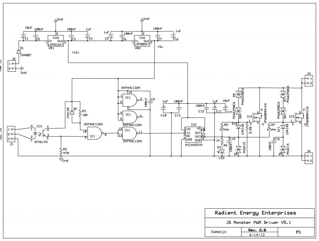
    ...
    Circuit diagram, seems OK so far.
    Usually components are oriented in a way that current flows from top to bottom or left to right. Thus anybody can read it easily. Therefore I suggest to rotate the regulators 180 degree.
    JS

    Leave a comment:


  • sampojo
    replied
    Wheel has been re-invented

    Originally posted by bourne View Post
    Good evening Everyone.

    I have been reading this thread along with the motor thread for some weeks now and I must admit it has been a roller-coaster of enjoyment as well as an eye opening lesson in just about everything.

    I know I am joining the party at a late hour but I thought it was time I introduced myself and said hello and thank you. Thank you for getting me interested in so many things I have been meaning to do for some years now.

    In the last few weeks I have bought my first Arduino and have been introducing myself to the programming language. There has been a few evenings of nothing but little blinking LED's, great fun !!

    The other thing I have been having lots of fun with is


    The free RS-Components PCB design software, I have been using Sir John's Monster Pulser circuit to learn schematics and then translating it to the PCB layout. Also, I have nearly completed a RS-Components parts list for the pulser. If anyone is interested, I could post it here when it's completed. I would have to add, a finished PCB is a few weeks away from being ready as there is so much to learn about PCB manufacture.
    The reason I am mentioning it is I believe, depending on your country you can get quotes for the boards locally but I have yet to reach that part of the process.

    I am slowly getting my head round all the principles UFO has been teaching here over the last 18 months. I have some experience with Bedini's SSG so no one has to prove to me radiant is useful, so it would be an honour to get involved with this research project. Even in a small way. I already have pages and pages of notes and have decided to Mod the razor scooter motors, I am sure I have seen re-wiring descriptions for that type some where in the motor thread and they seem readily available from Ebay shops here in the UK.

    Please don't think I am that guy who turns up at the party late and starts acting like he knows it all. My learning curve feels vertical at the moment and the best way to start to flatten it out is to get involved. I just hope I can get close to the quality of work and thinking I have seen so far.

    checkout OSHPark links here, welcome

    purchase Monster Driver PCB online at OSHPark

    Leave a comment:


  • sampojo
    replied
    Help on JS MD 5.1

    Originally posted by dione View Post
    Hi guys am new to this. Could anyone please help me on the schematic, i wana try and replicate UFO's circuit. thanks

    Hi Dione,

    page 67-75 I spent some time undestanding the circuit so I could eventually get the PCB made. I tried Express PCB first and then got it done at OshPark, which you can order them from now. But P67 post 1993 I list the CAD program, John's T3001 files, and ref materials. You can find several places in the last 20 pages about many details, some links need special attention, changes in R2 values etc.

    It helped me understand the T3001 symbols better to draw it in ExpressPCB tools which used symbols I was more familiar with.


    I tried to fill in a lot blanks in the BOM and cross ref'd the schematics and made an Excel file to help the building process. Its going slow, working on a big motor more.

    John Stone stepped Cornboy thru a lot of construction past 10 pages, check it out.
    Ah if it is just pulsing the coil to see purple radiant energy from original circuit using a 555 timer, well that is back before then Monster Driver, but the MD with arduino could be used for the same thing, and you would have an asym motor PWM too.

    Hope this helps and
    Last edited by sampojo; 10-10-2013, 03:26 AM.

    Leave a comment:


  • GChilders
    replied
    BT module

    @John Stone
    John I read the link that you posted and it was very informative. Apparently the firmware is what makes the difference between master slave and slave only with HC-05 being capable of master or slave and HC-06 being capable of master only or slave only, not having the capability of being reprogrammed by the user as the HC-05 is. I am assuming that we will need a slave for each Arduino processor. I.E. One for motor control commands and one for the data acquisition? There seems to be a lot of choices and large price range in these blue tooth adapters. Have read a lot of customer reviews and there seem to be a number of complaints on how difficult some models are to get to work and general lack of documentation. Well I think it may be possible to master slave the two Arduinos and then it may be possible that only one module would be needed. Need to study some more. Thanks for the info and good luck with your razor build.

    Cheers

    Garry

    Leave a comment:


  • JohnStone
    replied
    Originally posted by GChilders View Post
    .... has 6 pins and in the ebay connection it seems to have 4. I believe this is a transceiver slave module. Are you using a master or a slave module? I....
    Hi Garry,
    sorry for late answer.
    We will use slave modules as PC is the master.
    I decided for a module bein able to operate at 5V. It does not count if it has 4 or 6 pins. the two additional ones are for enhanced operation like external key preset and state pin.
    [IMG]http://www.ebaypa.com/albums/20120002/sku039535_1.jpg[/IMG
    I suggest this type above but I never operated it at Arduino myself. It is the best choice I could find redading plenty of post regarding Arduino and BT. It might be necessary to add 2 resistors in order to adapt to 5V Arduino 5VTX vaklue (10K/20K) bacause alle BT modules operate internally on 3.3V. Arduino is 3.3V level compatible for input.
    The choice above incorporates an internal 5V/3.3V regulator.
    You might want to consult this link or similar.
    All the best
    JS

    Leave a comment:


  • GChilders
    replied
    bt module

    @JohnStone
    John I am a little confused by the pictures of the blue tooth module. In the pictures in LN005 the module has 6 pins and in the ebay connection it seems to have 4. I believe this is a transceiver slave module. Are you using a master or a slave module? I am going to order all of the parts for the data acquisition system this week and just wanted to clarify what we are needing for this part of the set up.

    Cheers

    Garry

    Leave a comment:


  • JohnStone
    replied
    Hi bourne! Welcome!
    On order to flatten the vertical learning curve I recommend to pulse a coil first. This thread here is dedicated to those first learning event. You might decide to take a coil of a motor and pulse it - but do it. You need to disconnect it from all other windings in order to pulse just this single one.

    Regarding PCB and schematics: I appreciate you digged into PCB design. I designed monster driver on similar free package as well (Target3001). Later on I decided to continue for future actions with free Eagle package. It offers FULL functionality up to 80mmx100mm PCB size. It was not easy decision but I experienced that many contributors had problems with these dedocated is ECAD software packages.
    Apart that Eagle offers (some brand new goodies since last release):
    • It is one of woldwide standards in ECAD and therefore we can interchange our designs easily
    • direct link to LTSpice simulations software
    • direct link to electronic distributor Newark / Farnell. They are one of the great players with biggest portfolio of components and therefore we can refine our BOM from EAGLE directly
    • Oshpark is a PCB manufacturer accepting direct Eagle projects as input - no export to gerber / excellon format required (Monsters currently available originate from Oshpark)
    • last but not least we get plenty of components ready for circuit and PCD design.

    I do not urge you to go for Eagle but keep this ECAD program in mind. If you know Design Spark you will find very very similar procedures at EAGLE as well.

    Once again: Welcome to the party! Please post what your next experiment will be.
    rgds JS
    Last edited by JohnStone; 10-05-2013, 06:11 PM.

    Leave a comment:


  • bourne
    replied
    Good evening Everyone.

    I have been reading this thread along with the motor thread for some weeks now and I must admit it has been a roller-coaster of enjoyment as well as an eye opening lesson in just about everything.

    I know I am joining the party at a late hour but I thought it was time I introduced myself and said hello and thank you. Thank you for getting me interested in so many things I have been meaning to do for some years now.

    In the last few weeks I have bought my first Arduino and have been introducing myself to the programming language. There has been a few evenings of nothing but little blinking LED's, great fun !!

    The other thing I have been having lots of fun with is


    The free RS-Components PCB design software, I have been using Sir John's Monster Pulser circuit to learn schematics and then translating it to the PCB layout. Also, I have nearly completed a RS-Components parts list for the pulser. If anyone is interested, I could post it here when it's completed. I would have to add, a finished PCB is a few weeks away from being ready as there is so much to learn about PCB manufacture.
    The reason I am mentioning it is I believe, depending on your country you can get quotes for the boards locally but I have yet to reach that part of the process.

    I am slowly getting my head round all the principles UFO has been teaching here over the last 18 months. I have some experience with Bedini's SSG so no one has to prove to me radiant is useful, so it would be an honour to get involved with this research project. Even in a small way. I already have pages and pages of notes and have decided to Mod the razor scooter motors, I am sure I have seen re-wiring descriptions for that type some where in the motor thread and they seem readily available from Ebay shops here in the UK.

    Please don't think I am that guy who turns up at the party late and starts acting like he knows it all. My learning curve feels vertical at the moment and the best way to start to flatten it out is to get involved. I just hope I can get close to the quality of work and thinking I have seen so far.

    Leave a comment:


  • dione
    replied
    Hi guys am new to this. Could anyone please help me on the schematic, i wana try and replicate UFO's circuit. thanks

    Leave a comment:


  • JohnStone
    replied
    Originally posted by GChilders View Post
    ....how long did it take you to receive your monster drive pcbs from the date that you ordered them from OSH Park? ....
    It took about 8 weeks. I contacted via eMail very late and got answer. He suggested local customs might be the bottle neck. And ideed he seemed to be right.
    Unfortunately my private time slot is now gone and I can work on driver few time only. of dmage or malfunction.
    Last result was that 2 FETs can be controlled within 150 ns.
    JS

    Leave a comment:


  • prochiro
    replied
    Garry

    It seems to take six to seven weeks. You must have ordered just after JS ordered and are in the next batch, I hope.
    Dana

    Leave a comment:


  • GChilders
    replied
    Monster Driver PCBs

    @JohnStone
    John how long did it take you to receive your monster drive pcbs from the date that you ordered them from OSH Park? I ordered mine on 8/17 and still have not received them after six weeks.
    @Sampojo
    I have sent two unanswered emails to Neal at [email protected]. Do you have another method of contacting him or the business? I feel that I am at a standstill and growing more impatient by the day. I feel that 6 weeks is more than ample time. He hasn't answered my first email that was sent two weeks ago yet? btw I love the puller you modified to get the commutator off of the Baldor. Great idea! Looks like a great project!

    Cheers

    Garry

    Leave a comment:


  • Cornboy 555
    replied
    Originally posted by JohnStone View Post
    Today I retracted to my lab with a special brand of wine

    Cheers Cornboy! Excuse please, I had to rotate the bottle about 120 degree regarding origin in order to align it to my glass!
    and spend nice time with monster driver while taking thorough measurements.
    Current and future results will be found at lab note LN006. Up to now I took all essential scope shot along explanations but FET not being loaded at drain pin. My procedure is to go step by step in order to not mix artifacts making me blind for causes.
    Adding load will be somewhat more complex because load (especially load spikes) backfire to gates opposing driver actions. Another concern will be to prove protection circuit to act at strains as expected.
    I hope you can understand my explanations - else ask!
    Cheers!
    JohnStone
    Ahhhh, John, Shiraz is my favorite as well, LN006 i do believe will age nicely as well.

    I have a three acre vinyard, that is totally overgrown, and neglected, because it is a "down the track" project, and it is filled with cutting grown vines from Government and private collections, of French Hybrids, from the late 1800's, when the American native vine pest Phyloxera, all but wiped out the European wine industry.

    The French, imported Native American Phyloxera tolerant vines and cross bred them with the European species, to produce vines of exceptional vigor,(French Hybrids) so much so, that the vines didn't even require spraying with chemicals.

    After a while the government Declared that, it was illegal, to grow these new species, because it would send the price of wine tumbling, if the vines could be grown so easy.

    Now The French use the native American species for Rootstock, and Graft there original Varieties, like Shiraz, on to them.

    Warm Regards Cornboy.

    Leave a comment:


  • JohnStone
    replied
    Today I retracted to my lab with a special brand of wine

    Cheers Cornboy! Excuse please, I had to rotate the bottle about 120 degree regarding origin in order to align it to my glass!
    and spend nice time with monster driver while taking thorough measurements.
    Current and future results will be found at lab note LN006. Up to now I took all essential scope shot along explanations but FET not being loaded at drain pin. My procedure is to go step by step in order to not mix artifacts making me blind for causes.
    Adding load will be somewhat more complex because load (especially load spikes) backfire to gates opposing driver actions. Another concern will be to prove protection circuit to act at strains as expected.
    I hope you can understand my explanations - else ask!
    Cheers!
    JohnStone
    Last edited by JohnStone; 09-26-2013, 10:19 PM.

    Leave a comment:


  • JohnStone
    replied
    Hi ntc,
    The circuit to study is in thisV5.1 PDF. I took Cornboy publicly with me and posted the sequence of building and testing. Later on I will add my posts to PDF in order to issue a final version. But before I will do thorough measurements in order to verifiy all features requested. Up to now I found the micrel driver to be amazingly fast. This night I got 5ns rise time at free run and +1ns with one gate connected. This suggests that switching losses will be neglecteble even at high current. and we will be able to drive more than 2 FETs at a time. That is good news!!!!

    Regarding separate feeding the driver / oscillator.
    GND:
    Any circuit is not restricted to DC or low frequency but has all capabilties of RF. Usuall this is of no concern for blinking LEDS and similar actions. But our setups produces a vast amount of RF distubance and therefore we need to obey some precautions in order to get them below severe disturbance.
    BTW: We never would be allowed to sell those circuits commercially because of regulations because they are wild RF transmitters.
    One major intrusion of RF and artifacts rom high current is a bad GND system. Therefore I recommnd to have ONE central MASSIVE GND reference where you connect source legs of FETs, GND of motor GND of battery and GND of driver. ONE single point where the leads arrive in star shape.
    In audio applications you get humming if you do not obey those rules. Apart that you have the guarantee that you have no displacement currents traveling any unkonwn trace on GND level causing voltage differnces.

    You might consult this site additionally.

    Supply:
    similar but not so desasterous your power supply (+) behaves. It is bad habit if you share any PSU line of your oscillator / driver with high current traces. Therefore I suggest to use a simple cheap wall charger (or separated battery as separated PSU for oscillator, driver freeing it from any other part of pulluted areas of power circuit.

    I suggested 15 Volt minimum in order to get 12V regulator performing well. But 18V or even 24V or 30V will be OK. Please check voltage regulators for heat at higher voltage. One issue to be measured will be if we get any advantage by increasing 12V to i.e. 15V at gate driver. I doubt it but I do not know just now.

    As we investigate the unkown we need to eagerly build our setups in order to not generate multiple dirty artifacts thet cover our sweetspot we search for. Ic we can control the previously unkonwn we can check on how we can simplify i.e the supply circuits. The rule I to change only one parameter at a time and study its effects. But if you have a dirty setup you never will be able to study or control one singel parameter because you will have a feedback from power circuit and you will not suceed. Imagine the feedback of a speaker to the microphone... teh setup does well within certain limits und will runaway above a certain feedback rate. But at ouer setups we will not listen to feddbacks - we stand there blindly and disturbed.

    If you rework your circuit you may post a pic in order to enable me to comment. And feel free to ask. There are no silly questions but answers. The major goal isfor you to learn in order to enable you performing well by yourself.
    My concern ist to give all of you a solid basis in order to succeed.

    EDIT: I just measured my Micrel driver with scope and found oscillations. I replaced the GND lead of the probe by a very short wire and most of them were gone. Please note that such a wire of some inches causees disturbance. Therefore keep all wires as short as possible!!!! The best smooting of signals is to prevent disturbing them.
    JS
    Last edited by JohnStone; 09-24-2013, 09:58 PM.

    Leave a comment:

Working...
X
