This forum is preserved as a permanent archive. The community continues at eMedia Press.

Announcement

Collapse
No announcement yet.

My Motors got me to Tap into Radiant Energy

Collapse
X
 
  • Filter
  • Time
  • Show
Clear All
new posts

  • GChilders
    replied
    RadiantMotorControlVersion0.0.1

    @all
    I spent the morning writing a very boring tutorial on the RadiantMotorControlVersion0.0.1beta and is in my drop box. I hope this helps. Right now I am hopeful that this explains the motor control well enough to get started on experiments and how I arrived at the methods used in the program. The link is at


    Please do read the tutorial that I have posted so that you can grasp a path forward to our experiments. We actually have been doing quite well with hand held devices and some of the photography has improved considerably.

    @hitby13kw
    I really liked LightworkerI setup. He was demonstrating a toy motor but it had a really nice laptop that interfaced with his sensors and an interesting dashboard. I have an lcd and I can tell you there is not much information that can be displayed there and what is displayed there is very small. I don't think it will be of much use for the volume of information that we want to display. There are many good tutorials on the Arduino on the web. I prefer to devote the majority of my time to things that will specifically help us accomplish our goals here. Things that cannot be found elsewhere. We are a community and therefore each can help another. If you see a set up that you like then ask how they did that and the great thing about the arduino is that the sketches are easy to modify. I do consider these things to be peripheral to our vision here.

    @John Stone

    I looked at the sensors at the link that you posted and they look very interesting. I guess I agree with the idea of using the I2C protocol for communication to the sensors. I have gone through a couple of tutorials and understand the advantages of this protocol. I am wondering how much processor load the program in its present form is going to demand and how much future load it will need to take with the sensor activity. It is not very difficult to code for as most of the devices take care of the heavy lifting. I am exhausted and am going to take a break, I appreciate you running interference for me as I really don't want to rewrite code continuously to satisfy the various needs of all on the forum. Lets test what we have first and then move on. As you said we are here to build motors.

    cheers

    Garry

    Leave a comment:


  • JohnStone
    replied
    Hi Hitby, & ALL
    I knew this request will arise and therefore I wrote the other post today. I understand your desire but it is more to it. We need to account the big picture where we want to go omiting permanent reworks of HW and SW.

    1.
    We need to save digital pins for real time use. It would not help to populate now all possible pins and rearrange later on. We surely will return to any place of shortcuts done and repeat the long way!
    Of course it is very handy to have a unit completely undependent from PC and dedicated to a special type of test. But full command set would require a sophisticated menue programmed and none of us will have fun with it. It will be a mess.

    I vote for I2C!
    see your shield suggested as I2C
    Alternatively: What about having a LCD with 16 key keypad and still using 2 pins only? We can buy it.

    BTW: Highlight see ir temperature sensor for mesuring on distance - i2c oc course .


    2.
    For a programmer it is much easyer to use a serial command I/F in order to test a restricted button interface instantly. We can have plenty of commands and test sequencies along remote control via PC. So I vote this I/F is a must as initital one.
    Serial can be done by bluetooth spending some few bucks in order to isolate PC completely.

    3. -> ESSENTIAL
    What are the next 3 tasks we are going to perform with Arduino? Any agreements?
    Garry just works an the basic building stone. Thanks That is a great help. But we need to save and appreciate the effort of Garry in order to do any task only once!

    Suggestions:
    - Variable pulse patterns for finding the best pulsing?
    - Ramp up for saving FETs?
    - Reliable current measurement?
    - Logging of data on PC?

    Apart that Arduino can feed some data to PC and get your PC calculating and logging - where Arduino is too slow.

    We can not have all and not all at once.

    Let's talk about next tasks and later on how and with what tools to perform it.
    JS
    Last edited by JohnStone; 07-24-2013, 08:48 PM.

    Leave a comment:


  • Hitby13kw
    replied
    RadiantMotorControlVersion0.0.2 beta ?

    @Garry ~ Your first change request is on the books, an update that you might consider is to use an LCD screen instead of having to have a PC with an open window as the communication port with the Arduino, Think about the DFR0009 from http://www.dfrobot.com/index.php?route=product/product&product_id=51(the select button is free for new ideas) (and we all know what the reset button does)


    LiquidCrystal lcd(12, 11, 5, 4, 3, 2); // initialize the LCD library with the numbers of the interface pins original NicoPWNSwitch code
    LiquidCrystal lcd(8, 9, 4, 5, 6, 7); // define our LCD and which pins to use DFRobot.com for DFR0009

    Team, Thanks for your good work to date

    Hitby13kw

    Leave a comment:


  • JohnStone
    replied
    Current Sensors

    Design of sensor system:
    We discussed some items before in the thread but there was no urgent use. But now we approach to need it.

    - We need to take in account that Arduino is restricted in processing power an and pins. Therefore we need to take provisions to save pins for inevitable real time signals like pulsing, rpm, rotor position in order to process them by i.e. interrupts.

    - There are a lot of other sensor signals demanding no real time feature. They should be connected via a simple bus system. Fortunately there is one exiting and alive (see below)

    - Arduino is not a Ferrari hence I feel we will come to limits soon if we load it with pulsing and speed sensor / control (PID). Hence we should be prepared to get a second one (if required) for aquisition of electrical data, temp and others being outside real time requirements ......


    Current sensing:
    Some time ago we discussed the usage of Allegro's isolated current sensors ACS...
    There are different sources where we can buy cheap break out boards being ready to connect to arduino.
    They sell different ranges and uni-/bidirectional types. Bandwidth up to 100kHz - good basis for calcualting REALLY true RMS. Analog input pins required - normally.
    Alternatively we can use a I2C ADC (see below) 12Bit along that sensor getting more precision and freeing additional pins.
    We need to save pins for real time signals like rpm, position of rotor .......


    Sensor bus recommended:
    For other sensors I recommend to use genuine I2C bus sensors (also called TWI - Two Wire Interface). (i.e. temperature) I2C has an inherent addressing and thus we need to spend two pins only (Clock / Data). Additional I/Os is via bus possible as well.
    Others are Keypad / LCD shields, 12Bit ADC / external PWM shield 16 channels / programmable gain amplifier / accellerator / compass ..... see for example or here
    All those devices are available as break out board and can be purchased for some bucks. We do not need to provide those capabilities by our own followed by long dicussion on how to get the board running. Our goal is motors and not electronics.

    Pulsing:
    If we decide later on that Arduino is not very good in pulsing we can use a dedicated I2C PWM chip (free programmable, breakout board available)

    Learn about I2C / TWI:
    Intro to I2C

    Adressing is composed of an inhernet type address. If more than one sensor of same type connected tehre are some few pins available in order to discern them. Quite handy procedure!

    Program sample:
    Wire.beginTransmission(slave_address);
    Wire.send(byte1);
    Wire.send(byte2);
    Wire.endTransmission();
    ...................
    see I2C/TWI Arduino


    If you everred anywhere of Dallas single wire - forget it! No use in open communities. Expensive!


    Please understand these hints as existing paved playground around Arduino and others like Raspberry ..... We shall choose to pick those flowers we like and need in order to give HER a nice and friendly bunch of flowers.
    JS
    Last edited by JohnStone; 07-24-2013, 02:47 PM.

    Leave a comment:


  • GChilders
    replied
    Sensors

    @Hitby13KW
    If you have read the comments on the area of info update you will see a note that this area needs a lot of work. I felt that those that have sensors already and are using them already have sub routines and functions to map them to the input pins. It will be very easy for them to cut and paste these subroutines and functions into the sketch. They will probably want to continue to use these sensors. I and probably many others have not purchased all of the sensors necessary to fill all of these pins. lol. My main thought at this time was to finish the motor control and that actually took a lot more work than I thought that it would. I have built a very nice dashboard and serial monitor, that instead of typing the commands into, you can simply click on a menu button and the command will be sent to the Arduino and the Arduino will echo back the command to the monitor. The thing I am trying to provide with the pins in a certain order is that someone can easily hook up their sensors and paste in their code and with a little help from me can communicate with the dashboard to get their sensor information to the dashboard. So I am open for suggestions as to what sensors might be best for us to use and what quality is essential for the project. Keep in mind that this is a first draft with lots of blank spaces to be filled in. It is the very first beta version of this program. I will help all who need help if I can.

    I hope you read my post after you downloaded the program and downloaded the update that I talked to Dana about. Not necessary if you downloaded it after I posted the last post. Every thing is working properly now. Perhaps we can get Dana to get one of those great deals on a sensor package like he did with the ufo kit. At least I think it was Dana. Let me know what sensors you have in mind and if others have ideas. This is what I think is necessary with the pin outs although we may not need two temp sensors. I am as anxious to get the right sensors as you are.

    Cheers

    Garry

    Leave a comment:


  • Hitby13kw
    replied
    RadiantMotorControlVersion0.0.1


    my question is for the input pins

    pin A0 first temperature sensor pin
    pin A1 second temperature sensor pin
    pin A2 amps In sensor Pin
    pin A3 amps Out sensor Pin
    pin A4 volts In sensor Pin
    pin A5 volts Out sensor Pin

    What are you using as your sensor circuits? Did I miss it from an earlier post?


    Impressive work
    Hitby13kw

    Leave a comment:


  • GChilders
    replied
    mistake in program

    @all

    I feel a little foolish to admit this but I made some changes in the program when I was away from home this afternoon. So Dana if you would please download it again you will have a version that actually works properly.

    lol

    cheers

    Garry

    Leave a comment:


  • prochiro
    replied
    @ Garry
    WOW WOW WOW ... Looks like you have planed our activities for the rest on the summer. With tools like this how can we not find our answer. Cant wait for the controller to test this out. I have all the internals set in arduino already. Thanks...
    Dana

    Leave a comment:


  • GChilders
    replied
    RadiantMotorControlVersion0.0.1

    @Dana
    That is not exactly what I was looking for. I know how to convert an Integer to string and this will be fine for most of the items on the dashboard i.e. RPM, temperature readings are fine without any thing but whole numbers hence the use of Integer instead of double or float precision which gives values to the right of the decimal point. My hand held voltmeter has two numerals to the right of the decimal point. For some reason c++ include the conversion of doubles or floats until a very late version and arduino is not using this version. I think displaying the volts in and volts out, amps in and
    amps out in a familiar format not only looks better but is a more accurate measure of what the motor is consuming but also more accurate measure of what it is putting out of the generator. Anyway, here is the link to the arduino sketch ready to be up loaded into the arduino of your choice. I recommend before anyone uploads this they look carefully at the following pieces that need to be changed to your processor and motor.
    Setup Variables
    the two critical are the processor and numberOfBrushPairs put the ones that apply to your setup. Since capitalization and spelling are critical I recommend that this info is copied and pasted into the variable, do not forget the double quotation marks on each side of the processor name.
    the wiring must follow the layout described at the top of the sketch. this is the order that will be followed for each of the pwm pin arrays when the mode is changed on the fly and the pwm pins array is rebuilt on the fly.
    There is a large commented area that needs to be read completely in order to understand what the program is doing. This is the heart of the motor control. It is just above the sub process void motorSpeedRamp.
    This explains the use of the speed ramp to consume the values in the wait array and the various functions, sub processes, switch cases, and loops that
    are used to control the motor and how this is used not only at the start up of the motor but how at a latter point it will be used to trim load conditions automatically. and also how it turns control from the motorSpeedRamp back to the main loop motor control.

    There is a very large sub process that is commented out. For those who do not have a hall effect sensor or infrared transmitter receiver this program will not work very well for them because the program relies heavily on the rpm readings to determine the course of action that needs to be taken. I commented out this section because in no load or small load tests it should be completely unnecessary at this point of experimentation and there is a lot of program to absorb and manage before getting to that complication. It can be uncommented by deleting the /* before the sub process begins and deleting the */ after the sub process rpmCheck. This subprocess is called from the main loop and the second line of the motor control needs to be uncommented by removing the // in front of the call for the rpmCheck() sub process. This sub routine checks the last rpm reading and the rpm reading before to see if the rpm are falling or accelerating and then adjusts the duty cycle and wait periods to trim the motor speed.

    here is the link


    cheers

    Garry

    Leave a comment:


  • prochiro
    replied
    @ Garry
    When your files are in dropbox, click on chain link at far right of file name. a new screen comes and clink on get link. The link is at that point already in your copy/paste area. In a post here, press add a link and paste the link in the box that comes up.

    PS I use external power for everything, Except the Arduino. I was mentioning that If your processing program gets clicked off or the computer gets backed up or program stalls that your only recourse to get it going again and stop a runaway motor was to feed data to txt file and read back in at startup.

    Were you asking how to do a string to integer? If you were asking that, here is a line of code that shows ho to do that:
    String words = String.valueOf(Speed)+" "+String.valueOf(wait);

    Hope that helps
    Dana

    Leave a comment:


  • GChilders
    replied
    dropbox

    btw I pretty much know how to do this but do not know the names of the dropbox accounts in order to share with them. If I am missing a way to make them publicly available let me know.

    Cheers,

    Garry

    Leave a comment:


  • JohnStone
    replied
    Originally posted by Ufopolitics View Post
    ...

    John...I will ask you a simple question...

    Is it the same thing...Pulsed DC Amperage...and Linear/Straight Feed DC Amperage?

    Let's remember that the Positive where that Clamp Meter is/was hooked to, was completely a very fast Pulsing DC closing circuit with Motor Coils and Negative Channels...Right?...So...in this case of such very close pulses...it would not make a big difference?...say when at full max Duty Cycle of 24.90 each Gate.
    ...
    Simple question but no simple answer. Thinks get complicated and it is time now to explain:
    Our amps meaurements measure in fact the heating potential of a current - YES that is the true definition. Therefore it is very appropiate to heat a resistor and check the temperature comparing it with the effect from true DC current. That is exactly what the HP meter mentioned before did. see additionally

    Crest factor:
    1. DC current 4A 100% duty -> peak 4A / average 4A = 1 (crest factor)
    2. Pulsed square current 4 A peak / 50% duty -> peak 4A / average 2A = 2 (crest factor)
    3. Pulsed square current 4 A peak / 25% duty -> peak 4A / average 1A = 4 (crest factor)
    4. Pulsed square current 4 A peak 12.5% duty -> peak 4A / average 0.5A = 8 (crest factor)

    If clamp meters talk of crest factors they often end at crest factor 3.

    The items 1.....4. above relates to pulsing a resistor. But if we pulse a coil or worse - a motor things get more and more worse. There are wild jumps in current sometimes feeding current back. A meter needs to deal with these facts. Bad news that meters usually do not indicate out of expertise state! Unfortunately they still need the brain of their operator.
    Additionally we might get phase shifts between voltage and current (i.e. feeding by rectified supply with too small smoothing cap. Hence conditions get deliberately worse. We need to account for phase shifts if we calculate power. It is NOT multiplying true RMS voltage by true RMS current - sorry it is NOT. I once red a mail from TEK that even their top scopes have some minor flaws in power calculation.

    The notion and experience is that any differing condition, will get different flaws when reading our meteres if they stay out of their expertise. This fact makes me feel sad if I see very engaged experimenters presenting their vids feeling they measure correctly- but they are fooled and any expert tells them what I tell you now. But they do not tell it in kind words - if they do not believe in free energy!

    Now: What to do?
    1. You have funds to buy a prfessional scope along a current probe (clamp) for this scope. AND you dare to connect thsi treasure to your setup
    2. Add a low resistance choke in series with + lead followed by a big cap. It will smooth the wild jumps and we can measure voltage and current being calmed down BEFORE the choke. And we can do it with any cheap DC meter. A good choke is a fat transformer where the second winding is shorted.
    The drawback is that this transormer might prevent feeding back to the battery - might!! - possibly the choke is of no concern for longitudinal wave feeding back.
    3. Measure your batteries:
    Calibrate them:
    A: Get them fully charged to i.e. 13.5V - exactly
    B: Discharge them with definite current (similar to setup expected) and time. Calculate enrgy used.
    C: Recharge like A: and calcualate energy
    D: Repeat a: trough C: several times
    E: Calculate performance ratio

    Operate setup
    F: Run your Setup for certain time
    G: Recharge Batteries like A:
    H: Calculagte energy used with performace ratio

    This is the reason Bedini discharged a set of battereis while charging several sets of same batteries being discharged before. That is a real prove.

    4. Check your meter applying square pulses duty with different cycles to a resistor and get readings. Calculate average current and compare readings.

    ------------------
    I hope those facts above are not too disappointing for you. Unfortunately it is real . Just now I have no easy solution. I will torture my brain in order to find a simpler idea.
    JS feeling

    Leave a comment:


  • GChilders
    replied
    RadiantMotorControlVersion0.0.1beta

    I am sorry for the delay posting the motor control program. Have had new innovations to deal with and some snags in the communication protocols.
    @Dana
    are you using an external power source for the arduino or are you powering it with the usb cable? If you are powering it with the usb it will power down when the computer is powered down. Mine has a jack to provide 9 volts power or plug into any wall socket and the program should continue to run until the battery drains or the power fails. An uninterruptible power supply would be in order here.
    @lightworker
    I may have this wrong but I think that you are using a comma delimited string to update the info to your monitor. I am having a lot of grief trying to do something in c++ that is a piece of cake in c# and vb.net. How to convert a double or a into a string. I have searched the web and found solutions but none seem to work on the arduino. I have included the string class and string stream class and still cannot get them to convert without giving an exception. Point the way if you are accomplishing this and I will have this interface done tonight.
    @all
    I have the installed dropbox and dragged the file into it and clicked on the file to share the folder. I am not sure how to proceed at this point. The choices are share with none, doesn't sound like sharing to me, share with home group read only, share with home group read and write, share with specific people. I don't think we want to open it up for everyone to write to the program now. Possible key members helping with the writing of the software. I would like to invite Dana, Lightworker and John Stone to view the program in its entirety and to run burn in tests with the entire program and not just the little excerpt that I posted the other day. This is the heart of the program but there are so many other implementations that you do not have that will help each of the questions I have seen posted on the site today. The concept is well thought out and much larger than those few lines of code.
    @ufoPolitics
    The pulse modes can be much more powerful than the way in which they are being used currently. Once everyone understands the way this program works they will have a complete test platform for adjusting the timing of the pulses and the length of the time of the pulse cycles, and the amount of the duty cycle. So I will post it as soon as someone tells me how to choose the workgroup. By the way all changes can be made on the fly between modes and such.

    Cheers,

    Garry

    Leave a comment:


  • Hitby13kw
    replied
    Originally posted by Ufopolitics View Post
    Hello Hitby,

    Well...We are experimenting...testing into new fields, and things can always go South...However a couple of things I would like to suggest:

    First, and forgetting about amperage meters... I did not see the same Machine performance on this last video as we all saw in the previous one...and I am directly referring to Speed Factor/Power/Torque.

    In your last video, Imperial did not reach the 3596 RPM's...as it did in previous videos.
    Therefore, that derives some issues when you connected the ceiling lamps...and that is that you do notice (and you said it on video) a clear change on the sound pitch when dropping down.

    In previous video (S_208) Imperial reached 3596 ...and only dropped 40 RPM's...while lighting 100 Watts.

    Now on S_215 and last Video...Motor never reaches those very close to required speed (3600) or 3596...And this is very important issue here...the closer the speed to required ratio...the better performance of BOTH Machines, Generator would NOT become that hard to turn...and Motor would be running without stress.


    Resuming...Imperial was not as "Robust" here as it was before...

    Some reason why this change that you may think off?...Batteries did not get fully charged for that test?...were they fully charged when you did prior tests?

    One thing I have realized on this Machines...If they are not "fully satisfied"...and obviously generates a "struggle" within core...this will raise amperage.
    Yes ~ you are correct, the batteries are low, its been about a week since we put a deep cycle equalize charge on them, overdue ~ Ha we laugh at the idea
    Originally posted by Ufopolitics View Post
    1-Run a Test the simplest form you could...meaning, just Supply Batteries...and forget about the transfer to ramp up...just batteries...no PSU, and Batteries should be charged for test....
    Valid point
    Originally posted by Ufopolitics View Post
    2- If it would be possible and within your reach...to get another DC AMP Meter...(if possible a brand new one, if not see if you could get a borrowed one) and make a test with just that meter...no shunt, no Data Logger.
    I got a Klein AC/DC Meter, at Home Depot...it goes for $132.00 USD...and it is very precise .. A True RMS...this is important...it must be within True Tested Reading Measurement Systems codes.


    Originally posted by Ufopolitics View Post
    3- And here I consider the must important of all points...
    Even if your meter was reading AC Amps...the difference will NEVER BE that much as you have shown between two videos...(from 3 to 14)...and PLEASE...DO NOT DUMP THAT METER!!...it needs to be tested VERSUS the new one or the borrowed one...besides testing it with, say a PSU simple circuit...(Lamp and PSU) where PSU shows the Amps...


    Originally posted by Ufopolitics View Post

    4-Re-Check/Re-Test your FET's...in ALL Four Channels and see what is going on...


    Research continues . . .

    Hitby13kw

    Leave a comment:


  • Ufopolitics
    replied
    Machine that looks great!

    Originally posted by machinealive View Post
    Hello Team

    Hitman you are doing a great job. UFO, I can't imagine how you felt when you first discovered/ rediscovered this. Also, I gotta say how much respect I have for your patience, here, but also your patience you must have displayed working through this, initially. Incredible!

    Vince Lombardi once said " the only place success comes before work, is in the dictionary". You got the fighting spirit UFO, everyone working here has it, and as long as we keep working with purpose, success, it's a given.

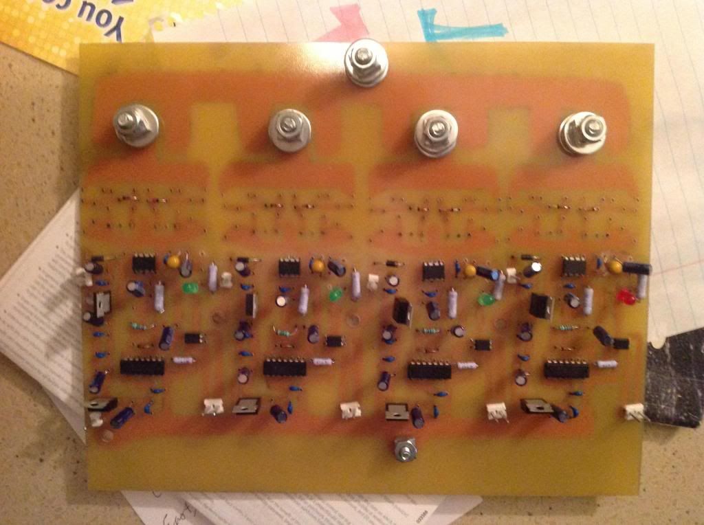
    I haven't stopped working. Here is my new driver board, not quite done, need a few parts, some fets. I'll be playing with other drivers till parts get here. Etching is a piece of cake, and so easy to solder, I am sold.


    If this doesn't do it, Dana's boards will be here soon enough. When I finally get this running, I'll know this sh$&, up, down, and the whole fu$&@&$ way around.
    And I wouldn't want it any other way.


    Later
    Machine
    Hello My Friend,

    Yes completely right and agree 100% friend!!...We All working here, have the desires and the fighting spirit...no doubt at all!


    Now that Board looks great!


    But does it work??!!...


    Was just joking My Friend!!...LOL

    We have to relax...every now and then...otherwise we could "fry" just like those FET's do...


    Warm Regards


    Ufopolitics

    Leave a comment:

Working...
X