
@ Sampojo
JS, Bro D(Donald Haas) an I have shown diagrams of proven circuits. Donald's circuits are split and I have given them several times, the last at post 1985, I think in this thread. I believe that any of these are good but JS's may benifit from seperation between sections and larger pads. If cost is important to you, etch just one of these first to test. Acquisition of the correct board is the easy part and only takes an hour. You are spending a lot of energy trying to derive the perfect setup, but this is done by building one, watching it work and changing things then make a better one. I have been thru that and believe that My circuit is good but could be reduced or split into four. To me, it is more important to have a strong, goof proof setup than have a tiny one that fits into a tiny box at this time. That will come later. I have no need for neon's as I did the testing JS required and I KNOW the circuit.
Dana
-
PCB mfg
If any of you are open to checking out an alternate PCB manufacturer with low prices, you might want to explore Eagle Cad Free edition and OSHPark.com. I have used them recently and with good results.
Leave a comment:
-
Ground...
Originally posted by sampojo View Post
Hello Sampojo,
I believe the correct answer as for the new layout of board...should be given by Dana or Sir John Stone...
I see it very nice and I believe it could save time and money by making a whole board then splicing it ourselves...that's what you meant right?
Now about Grounds, what we were talking about-that I can remember- was to ground referring as the Batteries Negative Source and to the FET's Switching side of circuit, and of course to FET's Source. As far as the Asymmetrical Imperial, it can NOT be grounded...since we are using the Negative Gates to Pulse them, and using a common Positive to all.The second item I am unclear about is grounds. I put a lot of pads around the corners, some on the ground path as is quite normal in board design. However Did I read some where recently that nary the grounds of the motor circuit and the controller circuit should meet? If this was a control box and it was all grounded to the chassis of an electric asym powered scooter, is that appropriate?
On a "second note"...remember Radiant flows back in all our Asymmetric motors...and it tends to go to ground or Motor Stator Frame if there is a short distance SHE could jump to...so, it would not be recommended to add this motor ground to electronics...but to a Chassis Ground of the vehicle just for "discharge purposes".
Regards
UfopoliticsLeave a comment:
-
JS
Hello Sampojo, It might be a good idea if you wait for John Stone to return and have a look at it all, he won't be long now, and he may have some suggestions that will help.
Warm Regards Cornboy.
Leave a comment:
-
Couple ExPCB ideas need feedback
With the expressed interest in having the FET board separate from the driver section, and myself having a jaundiced eye toward the extra setup fees at ExPCB, I thought I could tolerate the idea where I could take the hack saw to a single board and viola!, presto-chango boards are separated So to that end, here below is a demonstration of that idea showing room made to do it and cut along the green line. If this is considered a good idea it should be pushed just a little further where the pads in the middle are maybe brought together so that a 3-pin jumper could join the 2 with the proper cable. It would have the 2 driver connections and the ground would have to be brought up to a connector.
Should this design be pursued?
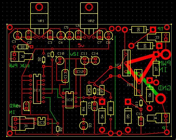
The second item I am unclear about is grounds. I put a lot of pads around the corners, some on the ground path as is quite normal in board design. However Did I read some where recently that nary the grounds of the motor circuit and the controller circuit should meet? If this was a control box and it was all grounded to the chassis of an electric asym powered scooter, is that appropriate?
Those default provided jumper icons look overly large and I need to look at a different footprint.
get at neons soon.
And another thingee, JS's desigh seemed to have symmetry on the heavy wires and all connected, with paths to FET1 and 2 equidistant. As you can see that is not possible with my green wire heavy trace. That would put the kibosh to this layout fast!!!
Edit: kibosh: meaning kill the design as incorrect!
Oh well I am going to go work on my motor now.Last edited by sampojo; 06-24-2013, 04:52 AM.Leave a comment:
-
Yep.
Originally posted by sampojo View Post
Yes Sampo, me likee, thanks for all you are doing.
Warm Regards Cornboy.
Leave a comment:
-
Neons...
Originally posted by sampojo View Post
Hello Sampojo,
Nice board!, great work!
The Neons go between Drain-Source of FET's...they will "absorb and monitor" the level of spikes according to brightness, now seen it in too much of the "Lady Colors"...is not good and your fet's will go anytime if so.
Regards
UfopoliticsLeave a comment:
-
Hi Cornman, neons sound really great and np to add along required traces. I have sufficient room for sure. Is this the same as at the beginning of this thread where it glows orange on hot voltage but if it is getting RE, it goes purple? Can you suggest exactly where to put them on the diagram?Originally posted by Cornboy 555 View Post
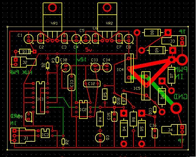
Concerning heat sink issue, I think I can just drop IC5 (second MOSFET) down to stagger them, not so much back to back as in the thumbnail? Thats about all you can get there without the upper and lower traces getting too close. Then a nice thick piece of aluminum can slide in-between with maybe even some fins as a tophat? You likee?Last edited by sampojo; 06-23-2013, 04:56 PM.Leave a comment:
-
G'day SampojoOriginally posted by sampojo View Post
Dana is writing the Arduino program to run the P56 motor to run the Macc Alte generator all the brush pairs are used to drive the motor we do not need to use any for a generator
Kindest Regards

Kogs still looking/learningLeave a comment:
-
Back in Time.
Originally posted by sampojo View Post
Hey JOEY, i had the (seeing) problem about pulsing all the gates, too, but it is all explained in the motor thread with UFO's excellent diagrams. If i had the time i would gladly hunt back the info for you and post the link, BUT alass.
Maybe if someone is going over that part now they could post a link.
One other thing @all, installing some neons across the fets to alarm you when voltage is becoming critical, would be a good idea? you would probably want 3 so when 300v or more is Returning back to say hello, you can back off, or check why this is not flowing from your output brushes.
I love seeing working lights on this stuff, visual things are very important, to help anyone who is watching, and trying to understand, what we are doing.
Warmest Regards Cornboy.
Leave a comment:
-
Re: Dana Post 2012
Dana, nice work on splitting the FETs off. Is that from the T3001 program? I could not get around too easy on that hummer of a CAD program! Definitely for the pros among us. Definitely an attractive idea separating the boards...Leave a comment:
-
@Cornman good suggestion
Hey Corn guy (reply from Pg 67 Post 2010)
I missed that one! Yeah I think it can go in there. I do see though that we are trying to operate at about 1/10 the JS design capacity, 100A's, arent we? Dana has reported cool operation, kinda limited test info still at this point. Machine has been losing FETs but he seems to be getting some voltage spikes.
And somebody please riddle me this, as Robin used to say to Batman.
(@prochiro @Ufo)
With an 8-brush Imperial, you have 2 motor brush pairs. So it would seem you should have only 2 driver boards, but pretty sure Dana is using 4 driver setups that use dual Mosfets, but on one big board he has manufactured. Guess I got a lot of studying to do on this 4-stator motor hook-up, which is the plan with my QP10 motor. Gotta go over all that arduino hookup and coding stuff! But a little illumination of this big picture to me would be a helpful steer in that direction
SOOO if lower amperage ops are reliable, I notice with this design the FETs could be brought back-to-back to share a heat sink if footprint considerations become important i.e. boxing the drivers up in a rugged compact control box.
But I think things can be wiggled around to be brought inline and make room for a bigger heat sink. One thing is certain with a 2-layer board design limitation to control cost is that the FETs must maintain the mirrored back-to-back installation you may notice in the current PCB. So an FET could be moved down and maintain the existing spacing between them along the Y-axis. I'll try again soon, as I need to start my honey do list asap.
Good eye Cornman! (check your PMs)Last edited by sampojo; 06-22-2013, 04:33 PM.Leave a comment:
-
@ Kogs
Congratulations and well done. Sorry about the diodes, will explain below.
@ All
JS is the expert on circuits here and all I am saying here is subject to his correction. I have vary bad eyes and had severe problems soldering a circuit with the extreme small size presented in the PDF. I also had several of the small copper lines burn and they are hard to find and repair. Sooooooooo, I enlarged just a bit and added much wider copper everywhere. I remembered that JS wanted us to send each fet in and out to a large buss and not combine them before getting to that buss. Sooooooooo, I really enlarged my copper at the pads and built up1/16 to almost 18 inch solder so the pads acted as a buss and held capacitance. The capacitance is a big issue some have forgotten. After having some diagnosis trouble, I put a two pin disconnect after the resistors going to the fets. Later I found that four boards was hard to handle at one time so I put the lower part of the circuit up to the fets on one board and all the fets on another. Bolting these two board together with two bolts made one board of the mess. By being able to separate the upper from the lower also gave me ability to work on the fet area and not mess up the lower part as well at fast diagnosis. After populating the boards I covered copper with all the solder they would hold.
This was not my first board as I made many before that and this is why I recommend that when you order an expensive board, you first etch it and make it work. These two boards actually cost me under five dollars to create minus the parts. I used one 12x12 inch clad on one side to do it. I got 15 of these on ebay for 45 dollars here.
5 Kepro Circuit Systems 12" x 12" Single Side Copper Clad Circuit Board | eBay
That is enough to make 20 sets of Monsters and the boards are vary strong. Two times stronger than any I have seem. When you guys put your circuits in motor vehicles or bikes, keep this in mind.
Kogs, I use 18 volts because I am using four sets of regulators at one time. Each regulator, when on, takes away mote than a volt. If you put in 12 volts, with four regulators you may end up with much lower than 12 volts at fets which will not hit them hard.
These diagrams I am presenting here are not the final product as we are in experimental stage. I see in the future a small purchased board which may be quite different than this. It does work and work well with NO weakness or problems anywhere. I present these as a starting point for your own builds only. The copper in the lower part does not need to be this heavy but the fet stage really does need this sort of structure.
This is the lower part, up to fets;
This is the fet stage;
I show multiple circuit here but you can separate at will.
Hope this helps some as we need many of these working in every country of the world.
DanaLeave a comment:
-
Kog's update
G'day All my Dear friends on these 2 ForumsOriginally posted by prochiro View Post
Last week I finished Making my John Stone's Monster Driver(thanks John it's a real Gem) it worked OK through the testing I was using a couple of purchased volt regulators. I did try some purchased Oscillators but one kind burned out 3 of them and the other kind I used previously when I tried to change the trim pot for an external one the solder would not take to it So I finished up with another the oscillator I originally made for "My Happy Motor" circuit.
I noticed that on Dana's Pic to Sampojo that the aux. power to be 18v not 12v so I bumped up the volts there to 18v and then I wired it up to My Happy motor circuit it started to smoke so I switched it off quick, on inspection I find that one of the Bidirectional diodes was burnt I took of the Mosfets and the Bi Directional diodes tested the Mosfets they were OK I replaced all of the Bidirectional Diodes and soldered them in and the original Mosfets .
I then reduced the Aux power to 12v connected the circuit to an Un modified "MY 250w motor" it was running it OK I then connected it up to a "MY1000watt motor" also un modified it went OK too the Mosfets were just a bit warm I tied to stop each motor by pressing a piece of soft wood against the shaft they both almost stopped but the amps of each motor only increased by a bit under 1 amp extra on each motor. and the amps to the driver did not really change.
I am very pleased with the results and will make some videos to show the results when I clean up my work bench and find my wife's Video camera.
I will now have to look at the Arduino and how it connects to the circuit and then make up the driver and use it on my Bicycle.
I will keep you all posted.
Thanks again UFO, John Stone Dana and all my other friends working to help each other on these forums
Kindest Regards to you all
Kogs working slowly but still workingLeave a comment:
-
In Line.
Originally posted by sampojo View Post
Thanks Sampojo, looks great, but i have never done a board before, one thing i noticed is that the fets would be better ( John Stone recomended ) inline to mount heatsink on both sides of fets.
well Done,
Warm regards Cornboy.
Leave a comment:


Leave a comment: