Announcement

Collapse
No announcement yet.

My Motors got me to Tap into Radiant Energy

Collapse
X
 
  • Filter
  • Time
  • Show
Clear All
new posts

  • sampojo
    replied
    Monster Pulser V5.1, latest and greatest circuit

    @worm

    Originally posted by wormtrojan View Post
    It is not that simple as the 339 circuit, the 555&393 circuit, or the double 393 circuit. But the 555's output can make the rising and falling edge sharper. The pot in IC1 is used to control the frequency, while the other pot is controlling the duty cycle. But when controlling the duty cycle, it is actually the "Width" that is being adjusted. So if we keep the second pot unaltered and dial the first one to adjust the frequency, the on time width of the output will stay unaltered. So we need to choose the C6-C9 capacitor carefully, and when adjusting the frequency, we need to adjust the duty cycle at the same time. It's pretty complicated, but has a better output performance. I hope I'm helping here. Good luck to everybody.
    Regards.
    Pretty good work, worm. Have you checked out the Monster Pulser V5.1 released by John Stone here on the motor thread and on this thread?

    Using the Arduino to do PWM with it, shifted completely off the 555. Now looking at Arduino interrupt capability to establish a governor capability to adjust to load changes.

    Here is the CAD program JS used to make the circuit, free: Target 3001

    Here is the primary CAD circuit.

    Production zip file posted by John Stone at Pg. 59 Post 1768.

    I don't know where I got this one but it is great, on my dropbox. MD_V5.1-prerelease.pdf
    Leave a comment:


  • sampojo
    replied

    Leave a comment:


  • lerameur
    replied
    Hi UFO,

    been holding off the Coil test. Was too anxious getting started with the motors. here is a picture with commutators and bearings removed, also the rotor spent time in an over to easily remove the copper wire, Here are the results. One magnet missing in the 2HP stator. But as, there is no way I can fit the two commutator on each end of the shaft.
    I may have to bring it to a mechanic work shop to have an insert made .

    Joel
    Attached Files

    Leave a comment:


  • wormtrojan
    replied
    Some information about this circuit.

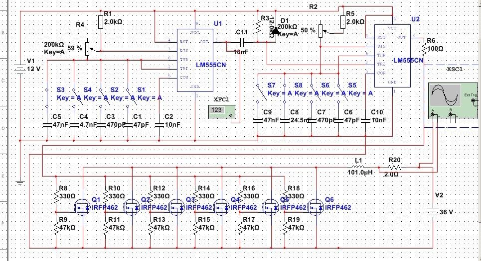
    It is not that simple as the 339 circuit, the 555&393 circuit, or the double 393 circuit. But the 555's output can make the rising and falling edge sharper. The pot in IC1 is used to control the frequency, while the other pot is controlling the duty cycle. But when controlling the duty cycle, it is actually the "Width" that is being adjusted. So if we keep the second pot unaltered and dial the first one to adjust the frequency, the on time width of the output will stay unaltered. So we need to choose the C6-C9 capacitor carefully, and when adjusting the frequency, we need to adjust the duty cycle at the same time. It's pretty complicated, but has a better output performance. I hope I'm helping here. Good luck to everybody.
    Regards.

    Leave a comment:


  • wormtrojan
    replied
    Sorry...

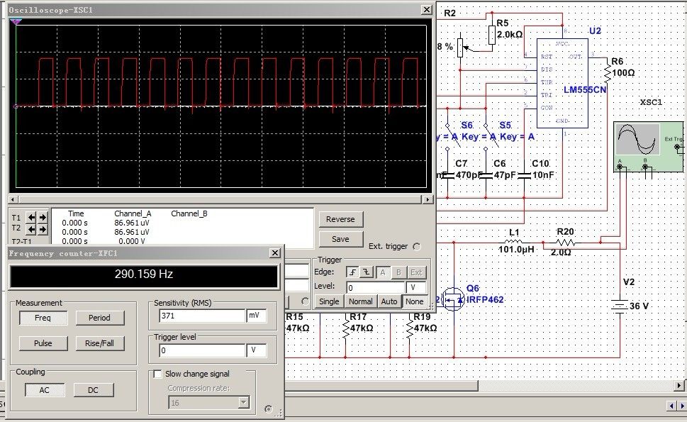
    Sorry that in the last pic, the frequency counter is covered by the oscilloscope,here's a new one~

    Leave a comment:


  • wormtrojan
    replied
    A new circuit

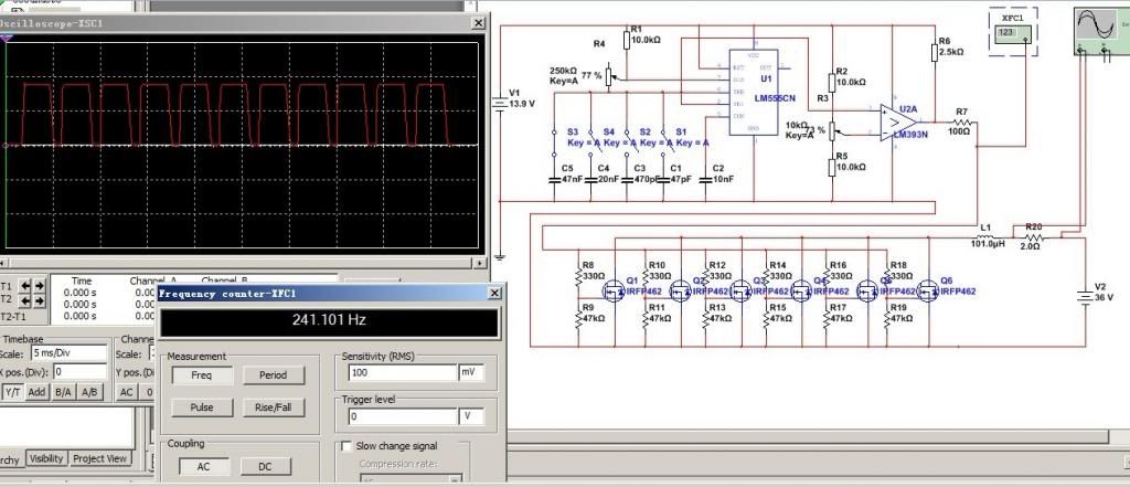
    Hey Ufo,hey everybody,the circuit issue is an old issue now,but I've just started to build this stuff. I remember that Ufo said that the rising and falling edge should be sharp enough,otherwise it is not certain what kind influence it would bring. Here is a pic that shows the waveform from the coil when using the 555&393 circuit.This circuit allows us to adjust the duty cycle and frequency independently.

    It is showing that the rising and falling edge is not that perfect. After some research I've found that it is due to the limit of lm393(at least as my personal opinion). So I've tried to make some changes to this circuit, making a circuit which allows us to adjust the duty cycle and frequency independently, meanwhile has the sharp rising and falling edge. I just replace the lm393 with another 555. It looks like this.

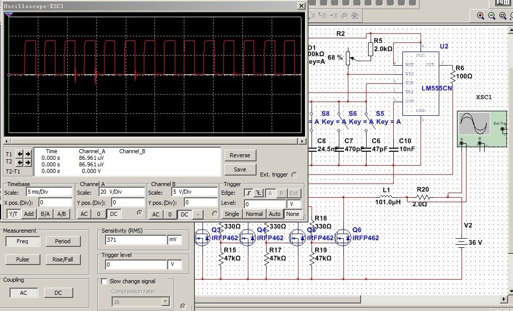
    And here is a pic showing the waveform from the coil and the frequency. It is closer to perfection.

    It should be noticed that the waveform is from the coil, which is powered by the 36v DC supply. It is not directly from the output pin of lm393 or 555.

    Leave a comment:


  • Cornboy 555
    replied
    Hey.

    Great to have you back John Stone, hope all is well.

    Warm Regards Cornboy.

    Leave a comment:


  • JohnStone
    replied
    Originally posted by tmasaitis View Post
    Hi John and all the rest of guys, I was monitoring all this thread and also doing some replications. I believe to handle FET gate capacity issue to drive multiple FET's simultaneously should be helpful to use this IC ULN2801A-ULN2805A, it can be driven from arduino as well (that's where I have found it)
    to connect 1 FET per output, to keep up with switching speed. What would be your suggestions Mr. John ? it also can be stacked 2, 3 ,4 IC depending on Amperage requirements. 1 IC can drive 8 FET's.

    Tom
    Hi Tom,
    you can drive FETs by plenty of means and all will work fine IF they fit to application. I extended all my knowledge in posts before on why it is essential to switch fast and distinct. Driving severe motors like Imperial one with several hundred amps peak current does not accept second level driving. You never will lubricate a racing machine with salad oil while for driving very gently it will suffice possibly.
    My driver was developed on request and dedicated especially to Imperial driving or similar applications.
    Nevertheless I encourage to experience different driving schemes for lower power tasks. ULN series is one of my preferred ICs for simple driving all sorts of small power devices.
    JS

    Leave a comment:


  • Donald Haas
    replied
    Help for KOGS if needed

    Hey Brother Kogs,

    Please contact me via my email address for any questions or help with the above linked items.

    [email protected]

    I've etched them and got them to work very well and may be able to save you some time and grief.

    bro d

    Leave a comment:


  • prochiro
    replied
    Hello All

    For those wishing to see what I used to make the Quad pulser on one board here is the T3001 file. I did take out some of the components visually but all one needs to do is go to view, layers, and hide all layers but the wires and print on your etching paper (two copies) and etch. This is the lower half.


    This is the upper half.


    I showed these just as an example but you can modify your files any other way you want to.
    Dana

    Leave a comment:


  • tmasaitis
    replied
    Multi MOSFET Driver expansion

    Originally posted by JohnStone View Post
    Ufo requested for his current setup a four phase oscillator.
    Post
    Post
    I threw some components into the circuit and ask for discussion. It is what I intend to build.

    The reason for using a microprocessor is because the circuit with logic ICs is lots of wires to draw and one use only. A micro is much more precise and versatile to use.
    @Lester: Some suggestions for i.e. snubber circuit? Suggestions for additional protection?
    @Nico: Arduino connected correct? What about modified program? Where did you connect your POT / LCD exactly?

    TBD:
    • 555 NMOS (slow but 200mA source sink at output) or CMOS (fast but 8mA only) - needs to be tested
    • Control for dead time and frequency: Pot, digital pot or by simple terminal program from PC (USB)
    • Display required?
    • Option for current measurements required?
    • Use of reset at pin at 555 in order to prevent unintended firing of FETs while program downloed and aother actions.


    With some additions (voltge feedback) this circuit can peform as SMPSU - not high end precision PSU but suffitient in order to control the voltage for our loads from battery stack or welder. It depens on your requirements and your setup.

    JohnS
    Hi John and all the rest of guys, I was monitoring all this thread and also doing some replications. I believe to handle FET gate capacity issue to drive multiple FET's simultaneously should be helpful to use this IC ULN2801A-ULN2805A, it can be driven from arduino as well (that's where I have found it)
    to connect 1 FET per output, to keep up with switching speed. What would be your suggestions Mr. John ? it also can be stacked 2, 3 ,4 IC depending on Amperage requirements. 1 IC can drive 8 FET's.

    Tom

    Leave a comment:


  • prochiro
    replied
    @ kogs
    Here is Bro Donalds version for T3001. He has split the Monster into two parts and thus files.


    Dana

    Leave a comment:


  • prochiro
    replied
    @ Kogs
    JohnStone sent me his file some time ago but I need to find it in my computer. Here is what I can find at the moment, its a start.


    Dana

    Leave a comment:


  • iankoglin
    replied
    Dana's replication of JS's Monster Driver

    Originally posted by prochiro View Post
    @ Sampojo
    I see you may be looking at different versions and getting confused.
    Those diagrams were confusing for me and are not complete as per version 5.1-prerelease PDF is. I would set up the parts as per the latter file shows and hook her up. If you want a cad file for T3000 I can send it to you. T3000 is free and easy. the file there is ready for sending out to production.
    Easy, easy, easy.
    Dana
    G'day Dana
    I like your monster driver setup circuit
    I have not been able to find any T3000 file of this circuit
    Please could you send me your T3000 file of it I would appreciate it
    I would like to make a copy
    I have purchased a "PCB Fab in a Box" it works great
    Kindest Regards

    Back at it again

    Leave a comment:


  • prochiro
    replied
    @ Sampojo
    JS put the R2 in as an if you need it type of thing, I think. I have not used it and taken it out of later of my versions. If your are talking about the opto setup, from your Nano PWM pin 6 goes to the opto pin on the lower left in the diagram I sent you. Then from the Nano Neg. pin goes to the opto lower right pin. When using more negative leads than the Nano actually has, at first set up a small Plug in board to use as a terminal for all the negatives to combine. for example you have negatives from each of the three pots, one for each Monster circuit (4), and at least one more as common ground to your battery. So at the minimum, you need 8 negative pin locations but the Nano only has 2.
    Now the Nano also only has one 5V output so I recommend at first also do the same for the positive pins as you need at least three pins there for the pots.
    I have set a project board on top of the Arduino into which I put both positive and negative female pin rows as well as mounted the pots.
    For now just do one circuit and get it down. Feel free to ask for help anywhere. I think that if you know how to etch a PCB that would be the place to start but for the cost, getting a few from professional dealer is good. If you do get them made please send me at least a printed photo or T3001 file so I can double check so you get what you want.
    We actually should get JS's circuit made up as it is in the 5.1 PDF to spread around for testing in more places. I think I will draw it up with larger wires and get some soon. After testing then we could all order from that place what each of us need. These boards are easy but have held us up for too long. It is not possible to improve them unless we all have the initial setup running.
    Dana
    Dana

    Leave a comment:

Working...
X