

-
Hello Holbi,Originally posted by Holbi View Post
Yes, I just noticed that this morning...missing all those nice 3D Drawings...
All you need to do is Edit your post and reload the new links to those images.
Then I will re quote your post in my answer, coming out with the new links...
No problems...more organization...we need it for so much material ahead of Us...
Regards
UfopoliticsLeave a comment:
-
I am sorry
Hello Ufopolitics,
I am sorry. I have just found that I am able to sort in my Photobucket uploaded images into different albums, and I arranged the uploaded images.
This action is unfortunately killed all link what was used by you quoting me.
I am sorry.Originally posted by Ufopolitics View Post
Kindest regards:
HolbiLeave a comment:
-
Hello Ufopolitics,
Thank you for the acknowledgement on 3D modelling.
Originally posted by Ufopolitics View PostCorrection: Unfortunately the later instrumental measurement do not prove the OU operation.By visual observation this operation is OU with 5-7 C.O.P. Of course it must also prove by instrumental measurements. Only we must find how to do it.
Other notes: this lamp when it is connected to the 220-230 V AC main a quite hot during operation.
Connecting to the radiant/cold electricity output terminals of the above mentioned basic circle, the fluorescent lamp was quite cold during it's operation.
I was not able to measure the power consumption of the fluorescent lamp connecting to the radiant/cold electricity output terminals because my handy meters practically did not show anything.
Only visual observation showed there is something different that we usually meet in electronics.
To-Do for the upcoming period: To develop a proper device to measure characteristic of radiant energy flow, such as direction, polarity, frequency, current, voltage, power etc. The traditional instruments are not valid for this type measurement.
As the traditional electricity (let we call - using Tesla terminology - the traditional electricity: "negative push type electricity") is measured by indirect methods only (nobody had seen flowing electrons inside the wire) as this new "PULL type" electricity (named radiant/cold electricity also) can also be measured by some indirect effects, we must find these effects only.
Regards: HolbiLeave a comment:
-
Whatcha mean man!
Yoh Bro!...wassup?!...what U mean where is radiant??!!...dontcha see that radiant Man?Originally posted by JohnnBlade View Post
Is everywhere around Us all ...just feel it ...she will come to you Johnny!
Peace Friend
Take care
UfopoliticsLeave a comment:
-
Awesome 3D
Hello Holbi,Originally posted by Holbi View Post
Awesome 3D Modeling!...isn't it wonderful to make it virtually first...being able to turn it around and around?...Yes, that is it.
Completely agree also...the adding of Magnetic Fields from generating coils needs an expanded area to propagate at common gap.My opinion is the common magnetic path should have biggest cross section then the individual generating coils magnetic path. It can help to collect magnetic particle, they also like to flow into space part of smallest resistance.
Yes, I realized that...and actually I believe the "spool" to house that Coil could be made out of a Non Ferrous nor Paramagnetic Material...like plastic...or mica....anything EXCEPT Carbon Fiber!The "Output coil" is not shown in this picture. The generating coils are symbolized by the green cylinders.
I believe so...however some simple testing should be made with plain solid ferrite cylinders and some neo's to check if there is any loss compared to steel rods.Is ferrite suitable material for the core?
It is true there are not off the shelf ferrite core similar to this, but ferrite is powder metallurgy products, so it can be produced.
Definitively that gap is important, it will define the magnitude or amplitude of the Hot Magnetic Field...which is the bait for Radiant, so we could make gap adjustable through some moving and locking end pieces, similar to the ones you have in grey cylinders at top and bottom.I think the distance from N to S poles in the common gap is also important parameter.
Yes, absolutely, I noticed you have moved down the generating coils to a perfect center alignment which is great...as it levels with the common field gap...Those final touches you obtain only with 3D Modeling...you have all views in one model...excellent!In case of ferrite core it can be produced with to parts North and South and the join between these 2 parts should be in the center of green, generating coils.
I see it Glowing in Purple light already Holbi...What is you opinion?
Kindest regards, and thanks for advance for the answer.
Excellent work like this leads to crystal clear communications!
Kind Regards and great to have you here with Us all Holbi!!
UfopoliticsLast edited by Ufopolitics; 04-27-2014, 07:12 PM.Leave a comment:
-
Leave a comment:
-
Geometry for the Radiant Energy system
Hello Ufopolitics,
Thank you very much for the draft of redirecting core system.
If I understand well we need something like this (for 4 generating coils):Originally posted by Ufopolitics View Post

Here is in other view:

or

The equidistant from N1-...Nx and S1-...Sx to the common gap is OK.
The equivalent volume and mass of North and South poles is OK.
My opinion is the common magnetic path should have biggest cross section then the individual generating coils magnetic path. It can help to collect magnetic particle, they also like to flow into space part of smallest resistance.
The "Output coil" is not shown in this picture. The generating coils are symbolized by the green cylinders.
Is ferrite suitable material for the core?
It is true there are not off the shelf ferrite core similar to this, but ferrite is powder metallurgy products, so it can be produced.
I think the distance from N to S poles in the common gap is also important parameter.
In case of ferrite core it can be produced with to parts North and South and the join between these 2 parts should be in the center of green, generating coils.
What is you opinion?
Kindest regards, and thanks for advance for the answer.Leave a comment:
-
Nice design...but it WILL NOT do the FULL redirection.Originally posted by Holbi View Post
[IMG]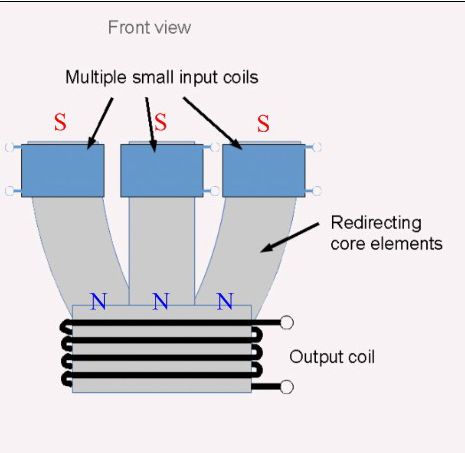 [/IMG]
Notice you are only "sending" or Redirecting North Poles to a Common place...Plus the Axis at Common Field are NOT centered, related to all individual coils...(at least not seen on Top View) it will then originate Four Independent Fields.
[IMG]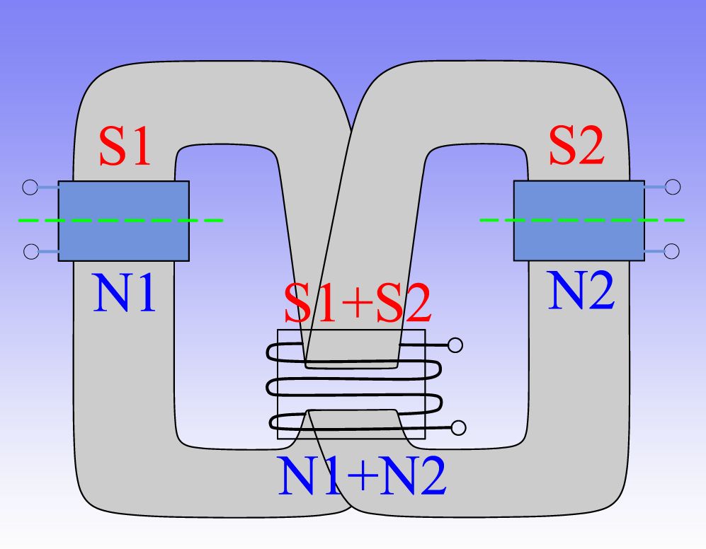 [/IMG]
Redirection Elements needs to carry both poles from each individual fields into the common Field like shown above...but that's not all:
S1 Redirecting Element MUST have same equidistant measurements from green line to end of Common Field Gap as N1 Element.
S1 Redirecting Element MUST be of same MASS as N2 Element...otherwise Poles will not be "balanced" (strength, size, area) at end gap.
S1 and N2 Elements does not need to be separated...but made of same core. However, at end extremes they MUST be separated with an air gap, in order to produce Field in that space.
Now, if we pulse both generating coils (light blue) simultaneously, we will obtain the Sum of both fields at common gap...BUT, if we pulse them at different times with equal feeding pulses...then Common Field would be equal to each coil Field along Time.
And...even though we are redirecting fields to a Common Gap/Space...we will always have an "original field" at each coil, at certain timing (beginning and end of pulse) will manifest stronger...realize it will take time (even very short time, nanoseconds) to travel through cores to end gap. This means we will get Radiant Fields ALSO at each individual coil. Therefore, We could collect Radiant Energy at each coil through diodes...
In the Coil displayed at Common Field (the one you named "Output Coil") we collect almost "Pure Radiant", because there is no direct input on that coil...so the induced Hot will be very weak...to our advantage.
The pulsing will be "Out of Phase" in order that there would always be -at least- ONE COIL ON, keeping a Hot Magnetic Field manifested at Core Gap, this will maintain Radiant in a "stand by" Space surrounding that field...while derivative fields from radiant will get "sucked in" through Off Timed Coils.
This way We are creating several "Gates" for Radiant to exhaust...while keeping a Main Field on at all times.
Note: I have just displayed two coils for sake of simplicity...simple Geometry...many could be added, reducing duty cycle per individual coils.
Regards
UfopoliticsLeave a comment:
-
Simple Geometries first...
Hello Holbi,Originally posted by Holbi View Post
My pleasure, however, still have to go back to My Machines...
I do, I have a few sketches, plus some other testing and models I have built a while back.As I understand well, there are few important key factors for the design:
- Geometry alignment of several small coils around a circle;
- Angle shift of these coils around a circle;
- Orientation of these coils - with their core - in order to project the resultant common radiant field;
- Pulse driving timing (pulse order, frequency, duty cycle, break before make or make before brake relation);
- And a common output coupler for all multiple aligned exciting coils.
Do you have a sketch of this idea?
I would suggest to start first by simple Geometries...without "redirecting elements" required, like a simple cylinder within other cylindrical coils, sharing same virtual shafts.
"Projecting" a Magnetic Field into Space is not simple...knowing we need both poles to keep their distance and away from its generator.
A Tesla Coil is a perfect and simple Geometry example...I have seen so many beautiful designs and builds of such great device...but none has mentioned anything about the Magnetic Fields alignment based on polarities and winding directions...the point is that if magnetic polarities are wrong...they will subtract tending to cancel...instead of adding.
How do you think a blind man would "see" this fields in his mind...knowing He could sense them by touch?How we can improve the ability to see these fields?
Can you suggest any drill or exercise?
A Magnetic Field could be felt by using repulsing and attract elements together...one on each hand...You could feel that solid mass range and limits into space...its curves...strength, elasticity, etc,etc.
Close your eyes...open a "screen" in your mind to transfer "touch to visual" in that screen...then try all possible angles.
About redirection...use cylinders of solid steel...measure with compass polarities once in physical and "no physical" contact with a magnet in different positions...
My pleasure Holbi.Kindest regards, and thanks for advance for the answer.
Regards
UfopoliticsLeave a comment:


Leave a comment: