This forum is preserved as a permanent archive. The community continues at eMedia Press.

Announcement

Collapse
No announcement yet.

Muller generator replication by Romerouk

Collapse
X
 
  • Filter
  • Time
  • Show
Clear All
new posts

  • Xenomorph
    replied
    Great work Toranorod !
    As you can imagine, i have a hard time seeing the rotor even moving with such a magnet set-up hehe.
    So i tried to make a simulation of it to visualize at least some of the flux lines. This doesn't include the most important part though, which is the the lenz magnetisation of the core (hard to do).

    Here the simulation gif: Tora simulation
    or on OU.com : Muller Dynamo


    At what RPM can you introduce the generator coil to see the effect?
    Is it at max RPM or a bit under?
    What is the strength of the 2 attached magnets? N42?

    Keep it up!
    Last edited by Xenomorph; 07-28-2011, 09:07 PM.

    Leave a comment:


  • minoly
    replied
    Originally posted by minoly View Post
    Hi Rod,
    congrats. that's some serious perserverence you have going there
    We're trying to make the "T" part of the iron core. how are they inter-connected? or is it just part of the core goes on top and part on the bottom, then bolted to the top of the "T"
    Is the leg of the "T" and the top of the "T" the same type of iron?
    Did you try w/o the "T" core?

    we attempted w/ welding rods for a core and no "T" yesterday w/ attracting magnets instead of opposing. the output of the coil increased quite a bit. after seing your pic. we flipped the magnets around and we get the same increase in output but less drag than yesterday.

    so we are hoping the top of the "T" also plays some role. We are using the SSG to turn the wheel, we may have to switch to something else to get more control of the freak.
    Thanks for sharing this.

    Patrick
    I should have previewed the post before posting. what I mean by increased output from the coil is.
    the generator coil produced more watts w/ the magnets in place than w/o them.

    Patrick

    side note I will have to reconfigure the magnets again to match yours. we have an all North out wheel so we used N out on the coil as well - we'll have to flip all those to match your south out. did you happen to try north out as well and found that south out was better?
    thanks again...

    Leave a comment:


  • minoly
    replied
    Hi Rod,
    congrats. that's some serious perserverence you have going there
    We're trying to make the "T" part of the iron core. how are they inter-connected? or is it just part of the core goes on top and part on the bottom, then bolted to the top of the "T"
    Is the leg of the "T" and the top of the "T" the same type of iron?
    Did you try w/o the "T" core?

    we attempted w/ welding rods for a core and no "T" yesterday w/ attracting magnets instead of opposing. the output of the coil increased quite a bit. after seing your pic. we flipped the magnets around and we get the same increase in output but less drag than yesterday.

    so we are hoping the top of the "T" also plays some role. We are using the SSG to turn the wheel, we may have to switch to something else to get more control of the freak.
    Thanks for sharing this.

    Patrick

    Leave a comment:


  • toranarod
    replied
    Originally posted by penno64 View Post
    Hi Rod,

    Would you like me to have a go at replicating ?

    I have those inductors on hand.

    For mags, I have a variety available.

    I do have an Arduino, but have not built the electronics or switching yet.

    Also avail is a PWM for dc motors that I can use to drive the rotor.

    Let me know. I have just about given up on Romero.

    Regards, Penno
    Yes if you have the time. i would enjoy that thank you.
    I will give you every detail i have on what i have done and experiments i have planed. help any way possible to get this replicated

    Leave a comment:


  • penno64
    replied
    Hi Rod,

    Would you like me to have a go at replicating ?

    I have those inductors on hand.

    For mags, I have a variety available.

    I do have an Arduino, but have not built the electronics or switching yet.

    Also avail is a PWM for dc motors that I can use to drive the rotor.

    Let me know. I have just about given up on Romero.

    Regards, Penno

    Leave a comment:


  • MonsieurM
    replied
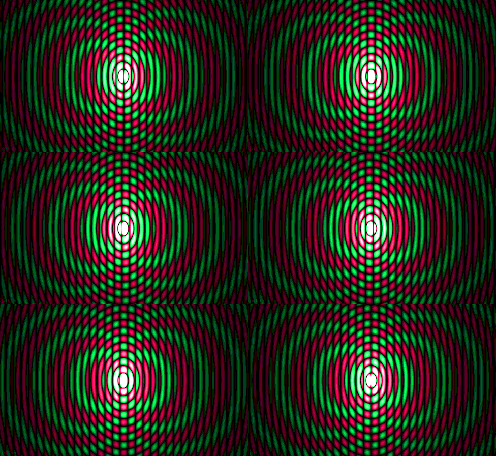
    rod, think of the following image as one neo magnet, now time that by your two

    Electrons - Spherical standing wave


    I can see your typing is filled with excitement, wish you best of luck

    Leave a comment:


  • toranarod
    replied

    Leave a comment:


  • penno64
    replied

    Leave a comment:


  • woopy
    replied
    Hi Rod

    congratulation for your pugnacity .

    And bravo for this great idea.

    will try something like this ASAP.

    Can you indicate on your pix the polarity of the side magnets versus the rotor magnet, and rotation direction of the rotor as it would help the replication

    Thank's for sharing

    And good luck at all

    Laurent

    Leave a comment:


  • toranarod
    replied
    Originally posted by marxist View Post
    Hi toranarod,


    I don't know, but
    if you increase the diameter of the disc/wheel and it turns at the same RPM as before, then you will automatically obtain a higher passing-speed between the magnets and the coils.

    Or in other words: if you use a larger disc, you don't have to go to such high RPMs to get the effect.

    That is to say: at lower RPMs you will obtain the same velocity of the magnets going past the coils as you have now.
    But what I really wanted to say is this:
    If you can document this in a youtube video I guess a lot of people would appreciate it.
    I would appreciate it.
    I will plan a video over the weekend. you would not believe the screaming noise this thing makes and hour or so with it makes me feel sick.
    you will hear this in the video so i wont say much.
    Just finished a new coil today and will post results later.
    cheers

    Leave a comment:


  • marxist
    replied
    Hi toranarod,
    Originally posted by toranarod View Post
    Good question? ...Question if I increase the size of the magnets by X 3 will it mean the speed needs the same increase? ...
    I don't know, but
    if you increase the diameter of the disc/wheel and it turns at the same RPM as before, then you will automatically obtain a higher passing-speed between the magnets and the coils.

    Or in other words: if you use a larger disc, you don't have to go to such high RPMs to get the effect.

    That is to say: at lower RPMs you will obtain the same velocity of the magnets going past the coils as you have now.
    But what I really wanted to say is this:
    Originally posted by toranarod View Post
    .... a jet fighter going through the sound barrier. there is this wall that gets crossed over. Then it all changes. ...
    If you can document this in a youtube video I guess a lot of people would appreciate it.
    I would appreciate it.
    Last edited by marxist; 07-28-2011, 04:56 AM.

    Leave a comment:


  • MonsieurM
    replied
    Originally posted by toranarod View Post
    Romero was right. very right
    All he was saying about what you should do. At the time it did not make sense. but it does now.

    Remember how he would say don't worry about the drive coils use an external dc motor if you need to. Focus on the generator coil.
    this is what I need to do. I will couple my rotor to a hi speed dc motor
    that has full speed control. I have a few out runner motors around the house.
    I am quite thrilled for you rod, you followed your instinct and it pays off ;

    Would it be too much trouble if you could collect some data, and post it, it could be invaluable for other applications....Congrats again

    Leave a comment:


  • toranarod
    replied
    Romero was right. very right
    All he was saying about what you should do. At the time it did not make sense. but it does now.

    Remember how he would say don't worry about the drive coils use an external dc motor if you need to. Focus on the generator coil.
    this is what I need to do. I will couple my rotor to a hi speed dc motor
    that has full speed control. I have a few out runner motors around the house.

    Leave a comment:


  • toranarod
    replied
    Originally posted by Zooty View Post
    You said the RPM did not change when the current draw was zero but did it change when the coil was not near the rotor?
    Good question? Here is the thing, it will not do the RPM i have listed above
    unless the generator coil is in place. the kicker is?
    you cannot bring the motor up that speed while it is there.
    its like a jet fighter going through the sound barrier. there is this wall that gets crossed over. Then it all changes.

    this is the most exciting thing i have ever had no my bench.

    I need to calculate the velocity of the magnets as they go passed the coil then see if it can be scaled up. Question
    if I increase the size of the magnets by X 3 will it mean the speed needs the same increase?

    Leave a comment:


  • Zooty
    replied
    Originally posted by toranarod View Post
    what you see is what you get. the photo show every thing.
    I have a working Lenz violation generator.

    I have just ordered a few DC to DC
    converters.


    Unless those figures in red are loaded coil readings YES
    You said the RPM did not change when the current draw was zero but did it change when the coil was not near the rotor?

    Leave a comment:

Working...
X