
Hey just so everyone can see it, I analyzed Rod's numbers. Consider the control the measurements with no coils present. If we compare the second two data sets to that we find that we get...
-3.18% in power consumption and -0.36% in RPM with all coils present and open
-2.41% in power consumption and +0.64% in RPM with all coils present and 4 shorted
Man I hope that is enough... I guess it all depends on how much much load we can pull off the coils...
-
ThanksOriginally posted by toranarod View Post
If you have plenty of work don't study the diagram yet. I explain it very clearly in my slides, with mathematical representation (no calculus).
However, if you need a brake from building and wanna mind puzzle feel free to figure it out... Just don't think that you have to figure it out from the limited information I have shared so far. I am on slide ten of probably 15.Leave a comment:
-
Are you suggesting using a transformer between your generator coil and your load? If so, yep, a transformer is exactly what we need in our generator coil circuits, but nothing more I think. Sydney was correct here, but I didn't know enough to realize the importance of what he said. I will share more of the why, and the how as soon as I can get to it.Originally posted by Dave45 View Post
Originally posted by Sydney View PostLast edited by Shadesz; 09-28-2011, 05:41 PM.Leave a comment:
-
That is a really good result!Originally posted by toranarod View Post
 less watts than coilless config and faster RPM. Have you tested shorting your coils with diodes? You can self drive your generator like this:


You should use the proper polarity for your driver coils, and also use diodes between the generator coil and driver coils to prevent backward current flow. See if you can get a much higher RPM. If you use larger magnets you can drive more coils.
EliasLeave a comment:
-
My motor today
test so far.
No coils drive motor consumption. 23.54 volts 4810 mill Amps. 2802 RPM
with coils fitted no load 23.25 volts 4715 mill Amps. 2792 RPM
all coils fitted 4 coils shorted 23.41 volts 4720 mill Amps. 2820 RPM

Leave a comment:
-
some interesting work you are doing here.Originally posted by Shadesz View Post
I am still trying to get a picture of what you see in your concept.
I will read it over and study your diagram. I get what you want to happen but I am not sure about it in practice.
can you present an electrical schematic. I read need a circuit diagram
good job.. You really are working very hard very keep up the good work.
I will be following your idea with great interest
Leave a comment:
-
Good job!Originally posted by elias View Post
Now you may want to consider what we discuss in this thread if you are considering using a generator coil to power a different drive coil that uses repulsion.
I also think there is some promise to it, if designed correctly.
Leave a comment:
-
The Coils Driving Eachother
Hi
Well, as I investigated this matter much further I found out it might not be as simple as connecting all of the coils parallel, because at any point when one magnet is aligned, half the other magnets must be attracted and half the other must be repelled in order to make them drive the rotor, Thanks to Shadez:

For simplicity we assume that the magnets are in the same pole configuration, like N-N-N or S-S-S. A somewhat sophisticated circuit design is needed that can control the coils. When one coil is generating one half must be connected to it in way that it repels the magnets and the other half of them must be connected in a way that attracts the magnet, so that you get your rotor being driven by that coil, now we can see why muller was using advanced circuitry. It is better to control the coils by a micro-controller that we can selectively program it to make rearrange the coils at each phase, which we have got 15 phases, one for each coil in the picture above.
It is also obvious from all of the tests we have done before, that when you connect 15 coils in parallel, and while one is driving the other 14, what happens is that, the resistance becomes minimum and the phase shift gets much much closer to 90 degrees, so that the drag becomes almost non-existent to the driving coil. The other beauty is that when you switch off each coil you can gather the back spike at an output also.
To test this effect we can connect two consecutive coils parallel to each other, by a diode, that make only one coil be able to drive the other, so that it avoids backlash. Or even this can be extended to half of your coils where one of them drives the rest, simply by connecting it via diodes to the other coils, in that half. Therefore when one coil is generating it makes its current circulate into the other coils that are ready to be attracted to the core. The other half must be connected in a way that be repelled by the core as they are ready for repulsion. if We connect all of them parallel to eachother then they will cancel out and while one will help the other move forward the other will help it move backwards.
This is very promising.
EliasLast edited by elias; 09-28-2011, 09:19 AM.Leave a comment:
-
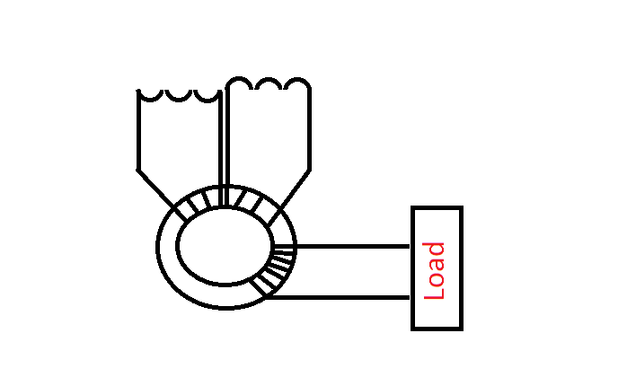
I doubt I can stay up long enough to finish this today so I figured I would give you a teaser of what I am working on. Here is a picture that I made for the presentation.
I have not been able to find any real explanation of the phase shift in an inductor, nor an explanation of how an inductor charges with a dc current. The following is how I believe it charges with a DC current.
As I finish my presentation I will show how that relates to the 90 degree phase shift using AC current (which I now realize we are NOT seeing in our generator coils, yet).
Anyways, here is the teaser picture. I wonder if anyone can figure it out just by looking at this???

Happy building!
Last edited by Shadesz; 09-28-2011, 06:53 AM.Leave a comment:
-
Q-vision,
Thanks for the confirmation.
@all,
I can't wait to finish and post this inductor phase shift presentation! It is so simple! It makes total sense why there is a 90 degree phase shift in ac current. And why, when you charge an inductor with dc, there is high voltage and zero current, and how the current increases in a logarithmic way on a dc induction circuit. Me thinks you will like the slide show I am working on.
Not only that, but I seriously think I know how we can remove half of lenz drag with one simple, simple circuit! (someone has already mention this on one of these threads, but I don't think any picked up on it)...and not only that, the simple circuit should allow us to easily pull a load off the generator coil while still removing half of lenz! Not only that, but if you get your magnet spacing just right, you could use the remaining 1/4 of the lenz wave to pull in your next magnet! Hence, it is so clear to me how we can reduce lenz by 75%! Imaging a generator with only 25% of lenz! Of course this is all theory currently.
I'll try to get this first part (inductor phase shift) posted tonight.Leave a comment:
-
LOL Australia going to waking up as i go to bed, that's the trouble with having a Global Team i guess
@ Shadesz,i agree that with DC, unless it was a square wave, then only the spikes would be picked up.
And having voltage without current is a good thing - if it's high voltage and could be stepped-down.Leave a comment:
-
Hello to allOriginally posted by Shadesz View Post
I have just woke up and read all the posts
looks like I got a busy day on the bench
some great ideas have been put forward I will start testing after breakfast.
We have good work group of guys here. this is always how OU was going to be researched.
Leave a comment:
-
ok sweet, but if it was DC the wire would only pick up the initial spike, correct? Sorry, I am working on that phase shift explanation, and want to make sure I have it right.Originally posted by qvision View Post
Oh, btw. I think I know why we can't get the 180 degree phase shift. But I think I may have a way to do it too... but why would we want voltage with no current?
Anyways, currently it appears like we don't have any phase shift at all in our pickup coils. Well kind of. I'll explain it when I get the idea better developed.Last edited by Shadesz; 09-27-2011, 10:21 PM.Leave a comment:




Leave a comment: