Originally posted by Shadesz
View Post
Announcement
Collapse
No announcement yet.
Muller generator replication by Romerouk
Collapse
X
-
@ Itsu !!
Sorry, i totally missed your post until just now. Excellent, really excellent. I learnt a few things from reading it and the links you provided.
So that fits with the RPM maths being far in excess of what people have seen on the bench, so perhaps Thane's theory is correct (i believe it) that the coil begins to act like a capacitor and simply doesn't have the current to produce the magnetic field that drags the rotor ?
Fantastic post Itsu - EVERYONE SHOULD READ IT !!!
Leave a comment:
-
read this and think on it.....
(see Dave's Proposals )
Constructal theory - Wikipedia, the free encyclopediathe constructal law says
The constructal law puts forth the idea that the generation of design (configuration, pattern, geometry) in nature is a physics phenomenon that unites all animate and inanimate systems, and that this phenomenon is covered by the Constructal Law stated by Adrian Bejan in 1996: "For a finite-size (flow) system to persist in time (to live), its configuration must evolve such that it provides easier access to the imposed currents that flow through it."

Last edited by MonsieurM; 09-29-2011, 01:13 PM.
Leave a comment:
-

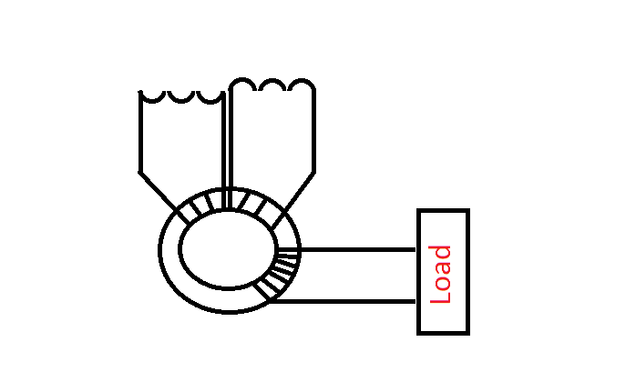
I modified the pic, but you guy's know more about electronics than me
Leave a comment:
-
Well, we know that the coil does NOT have to be high impedance to get acceleration-under-short-circuit, but to get acceleration with a real load, like a light bulb, high impedance is important.Originally posted by toranarod View PostI have acceleration under load of 4 coils at the moment trying to tune the other 5. now I see some merit in the time constant idea. but I do agree there is much more to it because it based a lot on the core materials flux. I think its more about the cores ability to hold on to the magnetic field.
If you test the switching of a load on half cycle will show some results of this.
If it was just time constant it would work with air cores and it does not.
because the magnetic field is created by a magnet not an induced current in the coil. its the load that is subjected to the T.C.
Fact we cannot ignore are?
1 there is a relation between coil resistance and coil inductance OK WHY is still up for debate.
2 RPM is a controlling factor and there for has something to with a TC but maybe not the TYPE we are looking for. Also mixed up with RPM is core and coil ratios and surface shape.
what are your thoughts on the effects?
I think the higher the coil impedance, the higher the load it can support.
There may be something in the ratio between L and R of the coil but, as you say, we need further experimentation.
Also, i notice definite effects from my drive coil (i'm using SSG circuit), because, even without a gen coil there, my diametric magnet will spin up to about 50% of it's maximum RPM (max is ~30,000) and the current draw is increasing, but then the current draw starts to drop until the magnet hits max rpm. This is without a gen coil in place so it must be an effect from my bifilar drive coil ...
I'm looking for a 1K pot so i can test it with a variable load, i will post results.
Leave a comment:
-
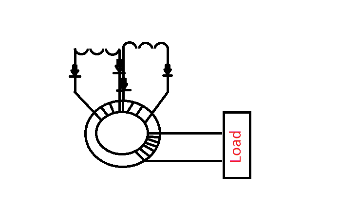
This allows the current created in your coil to move to the toroid and free's up the coils to move current.
And your rig is not load dependent.
Dave
Leave a comment:
-
I also believe electrical resistance causes magnetic resistance thats why I posted this.
Leave a comment:
-
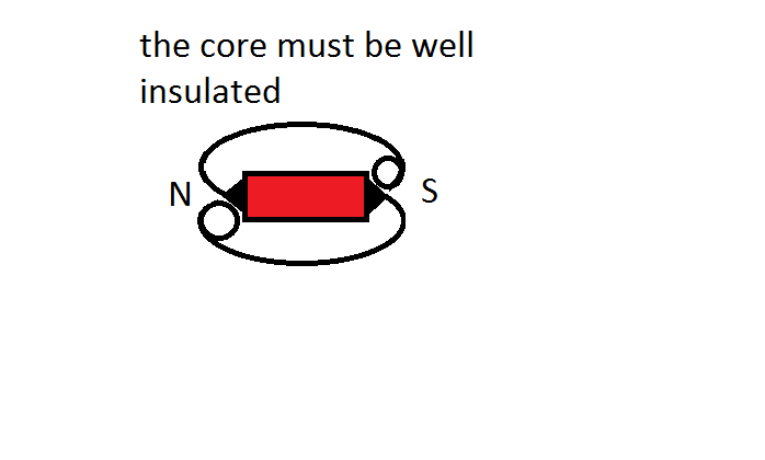
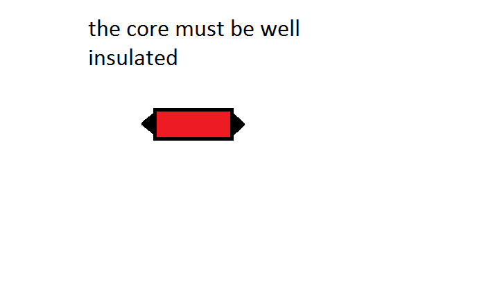
You know better than me, but try shaping and insulating the core I have a feeling this will helpOriginally posted by toranarod View PostI have never had good results when the core was flush with the coil. bill Muller seemed to do the same thing.
I havent been working on magnet motors I have my own project, but will lend a hand when I can.
Dave
Leave a comment:
-
I have never had good results when the core was flush with the coil. bill Muller seemed to do the same thing.Originally posted by Dave45 View PostAlso the core diameter should be as small as possible this will help magnify the magnetic field, I showed the core extending past the coil but it may be better if it didnt extend past the coil, this would allow the vortex created to be inside the coil, I would make the pointed tip of the core to be at the outer edge of the coil.
If you noticed in Ramero's rig the cores were small and the coils were shaped fat in the middle this allowed him to collect more bemf from the vector field.
I hope you guy's knock it out of the park
Dave
Leave a comment:
-
I have acceleration under load of 4 coils at the moment trying to tune the other 5. now I see some merit in the time constant idea. but I do agree there is much more to it because it based a lot on the core materials flux. I think its more about the cores ability to hold on to the magnetic field.Originally posted by qvision View Post@ All, really good stuff going on, wow it's getting busy !
@ Shadesz, i'm glad you are in disagreement with the time constant idea, because, as i said before, after i worked out the maths and put it in that spreadsheet, the RPM's needed to 'beat' the TC were far, far larger than what anyone needed on the bench to get the effect.
I wound a new coil yesterday and attached a miniature lightbulb as a load, the lightbulb lit quite brightly, the RPM rose by 5 Hz and the current draw went down by 5mA
If you test the switching of a load on half cycle will show some results of this.
If it was just time constant it would work with air cores and it does not.
because the magnetic field is created by a magnet not an induced current in the coil. its the load that is subjected to the T.C.
Fact we cannot ignore are?
1 there is a relation between coil resistance and coil inductance OK WHY is still up for debate.
2 RPM is a controlling factor and there for has something to with a TC but maybe not the TYPE we are looking for. Also mixed up with RPM is core and coil ratios and surface shape.
what are your thoughts on the effects?
Leave a comment:
-
Phase shift?
Hi all,
concerning the phase shift in a coil like we use on the muller, i wanted to find out
if we get any phase shift, and if so at what frequency this is starting to happen.
So i set up the following experiment:

For the bifilar coil, the winding which i measure has the following data:
L = 8.2 mH
R = 2 ohm
Self resonance measured using my FG and the scope = 142 Khz
capacitance calculated with the above data = 155 pF (using website L/C Resonance Calculator)
The bulb in cold status is 1.3 Ohm (it will not light up during the experiment)
The 1 Ohm resistor = 1 Ohm :-)
So total resistance in the used circuit is 4.3 Ohm
We can calculate the phase shifts using the following websites:
First calculating the reactances of the coil:
Inductor AC Behavior
Capacitor AC Behavior
Then calculating the phase shift with the above info:
9. Impedance and Phase Angle (see the flash app)
The calculated reactances and phase shifts for my coil are (200 Hz = 1500 rpm):
200 Hz:
XL = 0.0103 Ohm
Xc = 5.1 3Kohm
R = 4.3 Ohm
Phase shift = "V lags I by 90 degrees" (maximum capacitive)
2.6 Mhz:
XL = 140 ohm
Xc = 0.39 Ohm
R = 4.3 Ohm
Phase shift = "V leads I by 88.2 degrees" (this is what we want, but on the lower frequency please!!)
To check if my measured self resonance frequency of 142Khs is acurate i als checked for this freq.:
142 Khz:
XL = 7.2 Ohm
Xc = 7.2 Ohm
R = 4.3 Ohm
Phase Shift = "V is in phase with I" (Xc = XL so indeed resonance)
To confirm this i tested it myselve and made a video, which not exactly followed the above theory :-(
It confirms i have no phase shift on the low frequencies we use, and it also confirms
that we do get SOME phase shift on higher frequencies, but not in the way presented by the theory.
I see NO phase shift at all at lower frequency (200 Hz) while the calculations show i should have a max. capacitive phase shift (V lagging I)
Could be the capacitance is to low to "pack a punch"
And on the high frequency (2.6 Mhz) i get some phase shift like 30 degrees, but not the calculated 88.2
Probably there will be more resistance in the bulb at this high frequency (inductive reactance of the filament?)
Anyway, the above shows we have no advantage of this inductive phenomenon that should cause "V to lead I" on the low frequencies used in the Muller setup as it turns out to be highly capacitive on those low frequencies.
Video to be seen here: Phase Shift 2.avi - YouTube
Regards Itsu
Leave a comment:
-
Also the core diameter should be as small as possible this will help magnify the magnetic field, I showed the core extending past the coil but it may be better if it didnt extend past the coil, this would allow the vortex created to be inside the coil, I would make the pointed tip of the core to be at the outer edge of the coil.
If you noticed in Ramero's rig the cores were small and the coils were shaped fat in the middle this allowed him to collect more bemf from the vector field.
I hope you guy's knock it out of the park
Dave
Leave a comment:
-
@ All, really good stuff going on, wow it's getting busy !
@ Shadesz, i'm glad you are in disagreement with the time constant idea, because, as i said before, after i worked out the maths and put it in that spreadsheet, the RPM's needed to 'beat' the TC were far, far larger than what anyone needed on the bench to get the effect.
I wound a new coil yesterday and attached a miniature lightbulb as a load, the lightbulb lit quite brightly, the RPM rose by 5 Hz and the current draw went down by 5mA
Leave a comment:
-

This is what I meant by not allowing the other field from entering the core, insulate the core with fiberglass resin or some other insulator to strip the electrons from the magnetic field this will help keep the core from heating up.
I made a comment that a magnet motor was not the way to go, I hope you guys make me eat those words
Leave a comment:
-

I hope I give you guy's some idea's if you shape the core it should focus the magnetic field and also not allow the other field to enter the coil, insulate the core as well as possible this will keep the electrical field from entering the core and stop the core from heating up, good luck.
Dave
Leave a comment:

Leave a comment: