Announcement

Collapse
No announcement yet.

Donald Smith Devices too good to be true

Collapse
X
 
  • Filter
  • Time
  • Show
Clear All
new posts

  • Originally posted by soundiceuk View Post
    Absolutely marvellous John!

    Here are some very rare texts. Cheers Google
    The dark red and italic writing are different people but not Don.


    When using electromagnetic resonate flux energy systems, the electro side, when used, dies the classic heat death. Not so with .................................................. ............................. Magnetic Flux - Solar Wind, which spins - rotates the Earth. There is no Free Lunch, only the form changes allowing
    radiated energy to become available. A transformer changes radiated magnetic flux into usable electrical energy. Understanding these functions will be a start on Your Trip.

    Thanks for this aggragation
    But who explains this to mere mortals?

    I understood only that:

    1. Our meters are trimmed in order to measure the hot energy - i correct: the effects of it.
    The only true measurement is Gauss by gauss meters. Chaeap gauss meters measure up to 300Hz only. What will be the upper frequency we need to measure.

    2. As Zilano mentioned again and again there is soem magic in teh spark itself.

    3. Resonance devorces the marriage between magnetic and electric energy propagation making magnetic free.

    4. As T1000 and Utkin mentioned there are differnt ways inorder to hrvest OU.

    Some additional explanation for mere mortals?
    Experts spend hours a day in order to question their doing while others stopped thinking feeling they were professionals.

    Comment


    • soundiceuk , thank you for the pm and the info


      sorry i could not get back to you sooner ... got my mind a little tied up

      And i can see you are changing perspective as Don has been trying to convey

      hint imho : as some of you may know through various threads .... there are two poles to everything. .... in other words there is a mirror image to everything .... in our perspective (solar thinking ) a Capacitor is just that a capacitor .... but (soundiceuk noticed it ) there is also a "lunar" function to a capacitor its mirror (that is "Hidden" ) some call it Resonance ...

      Last edited by MonsieurM; 03-16-2012, 09:55 PM.
      Signs and symbols rule the world, not words nor laws.” -Confucius.

      Comment


      • Originally posted by soundiceuk View Post
        Sorry I haven't got back to your email yet John.

        Please can you explain what do you mean in the quote?

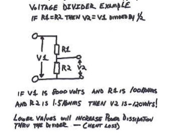
        To try and help with voltage dividers, here are some diagrams..... Hopefully they might provide something helpful to someone.


        http://www.energeticforum.com/attach...1&d=1331935022
        Attached Files

        Comment


        • Originally posted by Guruji View Post
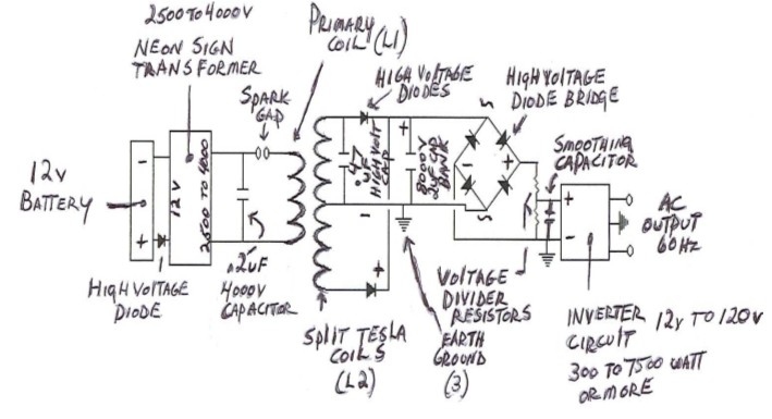
          What PWM are you using to the flyback? Do you have a schematic?
          That circuit very interesting.
          Regarding the voltage divider it should be to 12v not 120v for the inverter.
          Ok thanks guys
          I'm using 30 AMP Adjustable PWM Motor Speed Controller | eBay this one the Freq from the PWM dosn't seem to effect the NST freq. much...I'm not using the voltage divider in that schem. Also added the HV diodes not shown.......This PWM has a fairly smooth voltage adjustment from 0 to 100%. I don't really adjust the Freq of the PWM. I didt really get any difference from doing that..But it does let me adjust the spark gap firing... from a light crackle to and intence white and full the spark goes to a none productive purple. and with adjustable glass bottle capacitor I can adjust it too a nice quite Hissssssss....

          Randy

          Comment


          • Originally posted by JohnStone View Post
            The free end of the bridge rectifier confuses me. Either we can omit both diodes completely or it is the input for an antenna. Any suggestions available?
            Originally posted by dragon View Post
            I had the same thoughts earlier... http://www.energeticforum.com/renewa...tml#post184404

            If the NST ( 3) has a center taped secondary connected to earth ground then there is a return path and it functions like a buck converter. As drawn it cannot provide an output to the charging cap unless the diodes are "leaky" and providing a pulsed feedback. If there were an antenna at the DC- then it would entice the ambient to enter because of the spark gap. Maybe a large parasitic plate connected there would work as well.

            I plan to do some experiments with that circuit when time allows, I have several HV DC modules that should provide a reasonable test bed.
            Haha, you're both right! The antenna! Thats the secret! The cat is out of the bag.


            Look at number 9 on all the diagrams. Notice how everything else has a number but 9 has not. Where do you think it should be placed? hmmmm :-)

            Derating means detuning.

            Don said the answer was staring us in the face.

            So this is whats needed for the device to self sustain.
            Last edited by soundiceuk; 03-17-2012, 01:02 AM.

            Comment


            • Originally posted by soundiceuk View Post
              Haha, you're both right! The antenna! Thats the secret! The cat is out of the bag.


              Look at number 9 on all the diagrams. Notice how everything else has a number but 9 has not. Where do you think it should be placed? hmmmm :-)

              Derating means detuning.

              Don said the answer was staring us in the face.

              So this is whats needed for the device to self sustain.
              I wonder if its the tunning cap used for shunting the 1 secondary???? Good question

              Comment


              • Originally posted by Mr.Whip View Post
                I wonder if its the tunning cap used for shunting the 1 secondary???? Good question
                Yes I think item 9 is the tuning capacitor across one side of L2.
                I agree.

                Comment


                • Similar to a negative ion generator - it attracts the positive from the environment....

                  Connect the antenna to the positive of the battery and the DC- of the FWBR to the neg side of the battery....
                  Last edited by dragon; 03-17-2012, 02:43 AM.

                  Comment


                  • Nine

                    This pic is in the Vladmir Utkin PDF, but I thought that I've seen it elsewhere.

                    Number nine looks to be an adjustable R/C network of sorts.


                    Duane
                    Dude, you're curving my space-time.

                    Comment


                    • My setup

                      Hello Just wanted to show how my setup looks Its not pretty but its getting interesting... Whipschema.jpg

                      Randy

                      Comment


                      • Hello, everyone!

                        Hello, everyone!
                        I'm new here, I am Chinese. My Joule thief circuit can self-charge.

                        Comment


                        • Welcome Chang... do you have any schematics of your JT circuit?

                          Comment


                          • Originally posted by deggers View Post
                            This pic is in the Vladmir Utkin PDF, but I thought that I've seen it elsewhere.

                            Number nine looks to be an adjustable R/C network of sorts.


                            Duane


                            @ deggers
                            Thank you that clears the circuit connection

                            Regards
                            JJ
                            Last edited by myenergetic; 03-17-2012, 03:31 PM. Reason: Spelling

                            Comment


                            • welcome chang

                              Originally posted by CHANG View Post
                              Hello, everyone!
                              I'm new here, I am Chinese. My Joule thief circuit can self-charge.

                              please post some schematics and videos if any....

                              Comment


                              • Originally posted by deggers View Post
                                This pic is in the Vladmir Utkin PDF, but I thought that I've seen it elsewhere.

                                Number nine looks to be an adjustable R/C network of sorts.


                                Duane
                                The two npn transistors are backwards.
                                Rick

                                Comment

                                Working...
                                X