Announcement

Collapse
No announcement yet.

Donald Smith Devices too good to be true

Collapse
X
 
  • Filter
  • Time
  • Show
Clear All
new posts

  • There are 3 uses for external energy inputs:
    1) magnetic only relationship between multiple coils when electrical part play on secondary coils and does cancel itself so primary coil does not get affected
    2) Ionization with secondary emission effect
    3) Rapid particles dissipation with neutral particles entering system from outside.
    Last edited by T-1000; 03-14-2012, 06:54 PM.

    Comment


    • Originally posted by JohnStone View Post
      If you download from Linear Technology the data should be OK. If a manufacturer does not spend the "donation" to MS he will not have MS certified software. Then Windoze warns you with a wagging finger. If you experience this case - ignore it. MS got enough money.
      Ok John I downloaded the software. It'svery interesting. Did you try to see Don's circuit on this? Would be interesting.
      Thanks

      Originally posted by kajunkreations View Post
      Hey guys, Just like alot of you I have been experimenting in different ways to get Don's circuit working. There are a few people that have a working primary, myself included or at least I thought it is a working circuit. In the few ways I have managed to get the light to light up I was thinking I was getting somewhere considering every time I tried Don's way, I could not get the light to light up.
      Well I now think differently, after toying with Dons circuit, I think it is right even though the light doesnt light up. The reason for this is that when I use my circuit or Blue Serge's circuit I can light up a halogen bulb, but I get nothing with a florescent tube, and I can touch any wire on the L2 coil and not get shocked.
      Now when using Don's circuit the halogen bulb does not light but the florescent bulb lights anywhere within 2 feet of the device and I get shocked if I touch anything on the L2 side, and remember my setup is step down.
      So I really think there is something to this. I will post a video tomorrow

      Nolan
      KajunKreations yes there's something about L2 output. On mine I don't light a halogen neither only a 5w but wire gives sparks means high voltage is coming. Maybe with caps I can increase more amps

      Comment


      • On the FWBR in the diagram the "-DC" side is simply wasted, those diodes need not be there... if, however, you added an antenna at that point you would set up a parametric response and anything returned would be a bonus. A coil in the same position connected to the -DC and to ground adjusted to the same resonance as the circuit would also bring an ambient response.

        I just went through a series of minor tests and found by adding a 3 plate cap also gives a parametric response to the circuit. Input was at 500khz and the output was 1Mhz - similar to a hetrodyne resonse through the diodes. I've seen similar effects using tesla's pancake coils. Output, unfortunately, was quite poor during these tests though quite interesting.

        Comment


        • Originally posted by Guruji View Post
          Ok John I downloaded the software. It'svery interesting. Did you try to see Don's circuit on this? Would be interesting.
          Please take in account that a simulator does exact what scinece knows - mostly. In so far it is only one part of the chrystal.

          You will never see effects of longitudinal waves nor capcitors charging by being pulsed.

          On the other hand some known properties are ignored completely. You can adjust a pulse generator to 100 000 V pulses and draw 1000 Amps if you want. A capacitor will never get a breakdown and a resistor will never suffer on overheating. But you can know and measure if it dissipates mW or Megawatt.

          Nevertheless known scinence must not be ignored! A simulation gives you good insights in the principles of your circuit. Without knowing any formula you can incrementally adjust coils to resonance or filters. You can add tons of meters and scopes in order to get insight. You will learn alot.
          If you build your setup later on you will be quite near the requirements.

          I've seen lots of simulations but never did it myself. So I am learning LT spice as well. And it is sometimes not easy to include more components like i.e.NE555. But it is worth the effort!
          Last edited by JohnStone; 03-14-2012, 08:32 PM.
          Experts spend hours a day in order to question their doing while others stopped thinking feeling they were professionals.

          Comment


          • Regarding recent Don circuits. Please note that the transistors in the inverter are drawn reverse. This is not meant as instructable.
            Experts spend hours a day in order to question their doing while others stopped thinking feeling they were professionals.

            Comment


            • Don coils are not only distraction ! They are real but with missing magnetic path ! also they could be made air core also but not in Don presented embodiment.

              Here is ONE of missing patents you should read :

              Patent US4806834 - Electrical circuit for inductance conductors, transformers and motors - Google Patents

              Patent probably expired.

              Here you see where Don Smith could found inspiration. Just in case : I don't think the version with two opposite diodes can be patented as was shown by Don Smith in his books
              We are almost here.... In the end remember : humanity is about not hurting others by your ego

              If you can find my previous comments there was genious old video from youtube about electrostatic induction. We have to make EXACT ANALOGY in electrical terms and the crucial I suspect is the 'adjustable ground connection" like Don Smith explained.

              Without that all those simple Don schematics would be worthless, as you see only spikes of energy escaping to ground or air. I believe this is about impedance and adjustable ground connection plus voltage divider is the way to TUNE it !

              If you watch other thread this is all about the same , even 3 battery generating device : TUNE to catch energy from "aether" which is very high frequency and voltage skin effect electrostatic time compressed and what you like to describe it.....

              I hope I helped a bit.... I wish I could build it but I have a strange problem : when starting to build something I have too much concepts and they fight each other until I realize I didn't started - it's almost like if somebody is messing with my thoughts forbiding to construct working prototype.....

              Sorry - my english is not perfect....

              Comment


              • Originally posted by boguslaw View Post
                They are real but with missing magnetic path !
                Please listen carefully What D. Smith says about electric and magnetic part:
                Donald L Smith Inventors Weekend 2001 - YouTube

                And he is right on that point, more iron to magnet you bring, stonger magnetic field comes up. The iron clones magnetic field and does not weaken source - treat it as load to magnetic source. That is direct opposite to electric counterpart.

                Comment


                • Dons Circuit

                  Hey guys, here is a new video Working circuit 2 - YouTube In this video I show Dons circuit, or atleast as close as I can get to it. This circuit does not light the halogen bulb, but it does light up a fluorescent bulb. The effect is very different than the circuit that lights the halogen bulb. So take a look and give opinions

                  Nolan

                  Comment


                  • Originally posted by kajunkreations View Post
                    Hey guys, here is a new video Working circuit 2 - YouTube
                    The heavy caps are actually killing natural resonance. And in case of 40Khz to primary the secondary wire length to each leg should be around 7500m/4 -> 1875m.. Interesting

                    Comment


                    • Originally posted by T-1000 View Post
                      The heavy caps are actually killing natural resonance. And in case of 40Khz to primary the secondary wire length to each leg should be around 7500m/4 -> 1875m.. Interesting
                      The natural resonant freq of the L2 is 31.5 mhz. I calculated the 40K by using LC meter and LC resonance calculator.

                      Are you suggesting tune to natural resonance of L2 and run the same circuit?

                      Comment


                      • Originally posted by kajunkreations View Post
                        Hey guys, here is a new video Working circuit 2 - YouTube In this video I show Dons circuit, or atleast as close as I can get to it. This circuit does not light the halogen bulb, but it does light up a fluorescent bulb. The effect is very different than the circuit that lights the halogen bulb. So take a look and give opinions

                        Nolan
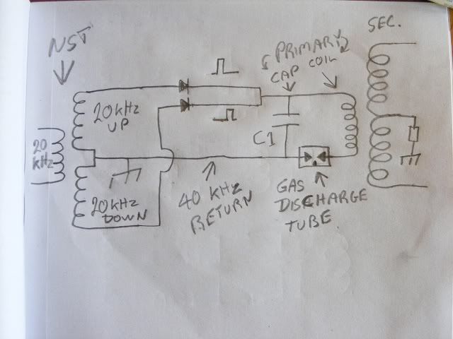
                        Hi Nolan, Can you try the circuit like this, and with the center tap grounded
                        as well ? Keep the tuning caps on the L2 as well. Are the tuning caps on L2
                        across both sides or across only one side to center tap ? I would put the
                        tuning cap across one side of L2 the positive side and tune using one side as
                        a coil so just forget about one side for the calculations, that will give two 1/4
                        wave sides to L2, if the resonance calculation is worked out using both sides
                        then the 1/4 wavelength will try to cover both sides of L2. I think we want
                        two 1/4 wave length resonators.


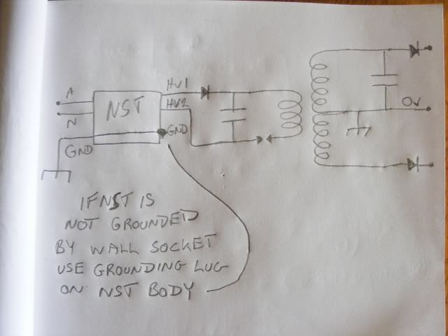
                        If that trips the Ground fault interrupter then just use one diode on one HV
                        side and the other side as the return I can draw a circuit if you want, no
                        probs.


                        P.S Here it is, this is the circuit I use so far with my small neon power supply,
                        this doesn't seem to trip the ground fault interrupter unless the spark gap is
                        made quite wide. I can take it to full power which is supposed to be 80 watts
                        but I only seen 65 watts leaving my battery to the inverter. Maybe it could
                        use 80 watts if powering a neon sign, dunno.


                        ..
                        Last edited by Farmhand; 03-15-2012, 04:21 AM.

                        Comment


                        • Vladimir Utkin ... latest

                          Hi folks with thanks to P.J.K here's Vladimirs latest up date and his addendum or if you'd rather wait I'm sure PJK will edit the info into his book in the next day or so http://dnp.s3.amazonaws.com/b/b2/VladimirUtkin.pdf and the addendum dnp.s3.amazonaws.com/b/b2/Utkin%20Extra.pdf
                          Whatever you can do,or dream you can,begin it.Boldness has genius,power and magic in it.Begin it now.

                          Comment


                          • Originally posted by JohnStone View Post
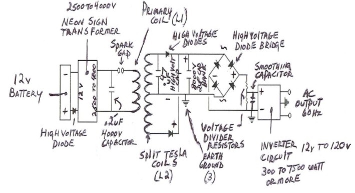
                            Regarding recent Don circuits. Please note that the transistors in the inverter are drawn reverse. This is not meant as instructable.
                            Sorry I haven't got back to your email yet John.

                            Please can you explain what do you mean in the quote?

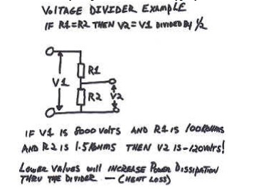
                            To try and help with voltage dividers, here are some diagrams..... Hopefully they might provide something helpful to someone.


                            Comment


                            • Originally posted by Duncan View Post
                              Hi folks with thanks to P.J.K here's Vladimirs latest up date and his addendum or if you'd rather wait I'm sure PJK will edit the info into his book in the next day or so http://dnp.s3.amazonaws.com/b/b2/VladimirUtkin.pdf and the addendum dnp.s3.amazonaws.com/b/b2/Utkin%20Extra.pdf
                              Isn't that what I've been posting all along over the last year or so.... ?
                              Last edited by dragon; 05-15-2012, 03:53 AM.

                              Comment


                              • kacher cap charge.wmv - YouTube

                                Comment

                                Working...
                                X