If this is your first visit, be sure to
check out the FAQ by clicking the
link above. You may have to register
before you can post: click the register link above to proceed. To start viewing messages,
select the forum that you want to visit from the selection below.
I'm using 30 AMP Adjustable PWM Motor Speed Controller | eBay this one the Freq from the PWM dosn't seem to effect the NST freq. much...I'm not using the voltage divider in that schem. Also added the HV diodes not shown.......This PWM has a fairly smooth voltage adjustment from 0 to 100%. I don't really adjust the Freq of the PWM. I didt really get any difference from doing that..But it does let me adjust the spark gap firing... from a light crackle to and intence white and full the spark goes to a none productive purple. and with adjustable glass bottle capacitor I can adjust it too a nice quite Hissssssss....
Randy
Hi Whip how did you do an adjustable glass bottle cap?
Thanks for sharing.
Hi Whip how did you do an adjustable glass bottle cap?
Thanks for sharing.
Glass bottle full of tap water. any metal rod threw cap with rubber stopper. 1" wide alum. strip taped to out side aprox. 7/8 around using tape you can slowly peal the foil away changing the capacitance . Once you find the sweet spot you can check cap for nf or pf value. wider foil more and less is less...Some of my bottle caps are just 1 wind of magnet wire on out side taped on....basic... Some us salt water but no need for lower pf caps. Randy
Last edited by Mr.Whip; 03-18-2012, 11:23 PM.
Reason: none
I'm using 30 AMP Adjustable PWM Motor Speed Controller | eBay this one the Freq from the PWM dosn't seem to effect the NST freq. much...I'm not using the voltage divider in that schem. Also added the HV diodes not shown.......This PWM has a fairly smooth voltage adjustment from 0 to 100%. I don't really adjust the Freq of the PWM. I didt really get any difference from doing that..But it does let me adjust the spark gap firing... from a light crackle to and intence white and full the spark goes to a none productive purple. and with adjustable glass bottle capacitor I can adjust it too a nice quite Hissssssss....
Randy
Hi Whip,
I assume you use a PWM controller out of a cordless drill. They work at a fixed frequency and change the duty cycle by the finger controller. Unfortenately the duty cycle needs to be adapted to your transformer and remain then stable. What we neet to adapt later on is the frequency. Look at earlyer posts. There was a schematic with a NE555 and TL81 where you could adjust the frequency and the dutycycle independently.
Experts spend hours a day in order to question their doing while others stopped thinking feeling they were professionals.
Glass bottle full of tap water. any metal rod threw cap with rubber stopper. 1" wide alum. strip taped to out side aprox. 7/8 around using tape you can slowly peal the foil away changing the capacitance . Once you find the sweet spot you can check cap for nf or pf value. wider foil more and less is less...Some of my bottle caps are just 1 wind of magnet wire on out side taped on....basic... Some us salt water but no need for lower pf caps. Randy
Did you try to change the level of water as well. It should work as well. For me it its theory only. Can you confirm that?
Experts spend hours a day in order to question their doing while others stopped thinking feeling they were professionals.
Glass bottle full of tap water. any metal rod threw cap with rubber stopper. 1" wide alum. strip taped to out side aprox. 7/8 around using tape you can slowly peal the foil away changing the capacitance . Once you find the sweet spot you can check cap for nf or pf value. wider foil more and less is less...Some of my bottle caps are just 1 wind of magnet wire on out side taped on....basic... Some us salt water but no need for lower pf caps. Randy
Thanks Mr.Whip I will try to adjust mine cause I did a wide aluminium foil on outside although still I found it better than my MMC that I've did to L1.
Yes John I will try that too.
I have only two MOT capacitors 2000v each. Can I work with these for the inverter circuit? If so what resistors should I do after the bridge to lower to 12v to the inverter?
Thanks for the info.
.....
I have only two MOT capacitors 2000v each. Can I work with these for the inverter circuit? If so what resistors should I do after the bridge to lower to 12v to the inverter?
Thanks for the info.
Those values are highly speculative. Don used big fat batteries of caps. So use all you can get. You need to find out what power output they can sustain.
They are spposed to selfcharge if pulsed constantly. Take in account that there are some notions that pulsed caps need to be conditioned for hours or days before they show the selfcharging effect. Don't stop your trial too early. The effect might depend on the make of the caps.
The value of the resistors depends on what voltage you get out of your capacitors. (see posts regarding voltage divider obove). The real function is highly speculative and needs to be explored.
Konforming normal electrical knowledge the deviders exceed any viable value of power. Imagine that you try to extract 1 KW 12 V out of 8KV. You will dissipate a multible of 1KW into the voltage devider.
Conforming "abnormal" knowledge: There are notions that the power and amperage occurs only in the secondary of your inverter while the primary is moslty amp less. Then the voltage devider needs to sustain itself only and can be in 100KOhm range. It will not see the output power - cold electricity - being convertetd in usable hot only after a the coil treatment in teh converter! There are notions that many converters were killd because this fact was overseen by their owners.
So please admit that we have no simple instructable here. We all are stumbling as well and explore unknown terrain. Don passed away and the jungle path closed behind him. We all are still searchers.
I assume you use a PWM controller out of a cordless drill. They work at a fixed frequency and change the duty cycle by the finger controller. Unfortenately the absolute on time (not dudy cycle) needs to be adapted to your transformer / voltage and remain then stable. What we need to adapt later on is the frequency.
Look at earlyer posts. There was a schematic with a NE555 and TL81 where you could adjust the frequency and the dutycycle independently.[/QUOTE]
Experts spend hours a day in order to question their doing while others stopped thinking feeling they were professionals.
Hello John. The PWM motor controler I'm using is the one I posted 30 AMP Adjustable PWM Motor Speed Controller | eBay It has a freq. adjustment Not the best range tho. The freq coming out of my NST remained aprox. 27.5k - 29.5k no matter where I set the PWM freq. or Duty Seems as if the NST has a buffering cap on inputs that dosn't let the circuit see the imput freq from the controller.I'll go check again and confirm.... Randy
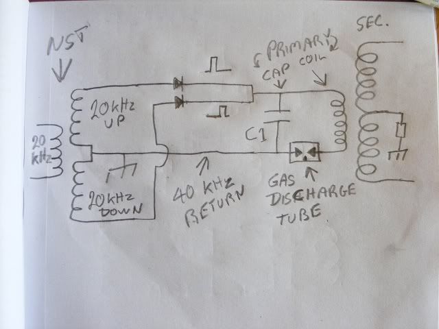
hey everyone, made a new vid after clueing onto the polarity dilemma with the center tap...
As most of us know, there is a neutralizing effect when using the center tap as Don showed on the double coil board (in question) And to get around that, ppl have resorted to cw/ccw turns.
Although that may work, i believe the following method is best.
You will see in the video that there is no more neutralizing happening, and more sparks than before with the properly parallel connected coils.
It is prob the most obvious thing, it is nothing new, but until now, i have never been sure about the advantage of merely reversing directions...
But using the parallel arrangement in the vid, i feel it is superior to anything i have done in the past. And i have done both ways, but not this one...
Truly makes use of the north end, or south end, or getting balanced use of both, ie high volts AND big orange sparks...
Those values are highly speculative. Don used big fat batteries of caps. So use all you can get. You need to find out what power output they can sustain.
They are spposed to selfcharge if pulsed constantly. Take in account that there are some notions that pulsed caps need to be conditioned for hours or days before they show the selfcharging effect. Don't stop your trial too early. The effect might depend on the make of the caps.
The value of the resistors depends on what voltage you get out of your capacitors. (see posts regarding voltage divider obove). The real function is highly speculative and needs to be explored.
Konforming normal electrical knowledge the deviders exceed any viable value of power. Imagine that you try to extract 1 KW 12 V out of 8KV. You will dissipate a multible of 1KW into the voltage devider.
Conforming "abnormal" knowledge: There are notions that the power and amperage occurs only in the secondary of your inverter while the primary is moslty amp less. Then the voltage devider needs to sustain itself only and can be in 100KOhm range. It will not see the output power - cold electricity - being convertetd in usable hot only after a the coil treatment in teh converter! There are notions that many converters were killd because this fact was overseen by their owners.
So please admit that we have no simple instructable here. We all are stumbling as well and explore unknown terrain. Don passed away and the jungle path closed behind him. We all are still searchers.
Ok John I will try with these MOT capacitors and see what I can get out of them. The amazing thing today I hooked them to my L2 as the circuit is and the charge went up in split of a second. This was'nt a phantom charge cause the discharge went back slowly.
hey everyone, made a new vid after clueing onto the polarity dilemma with the center tap...
As most of us know, there is a neutralizing effect when using the center tap as Don showed on the double coil board (in question) And to get around that, ppl have resorted to cw/ccw turns.
Although that may work, i believe the following method is best.
You will see in the video that there is no more neutralizing happening, and more sparks than before with the properly parallel connected coils.
It is prob the most obvious thing, it is nothing new, but until now, i have never been sure about the advantage of merely reversing directions...
But using the parallel arrangement in the vid, i feel it is superior to anything i have done in the past. And i have done both ways, but not this one...
Truly makes use of the north end, or south end, or getting balanced use of both, ie high volts AND big orange sparks...
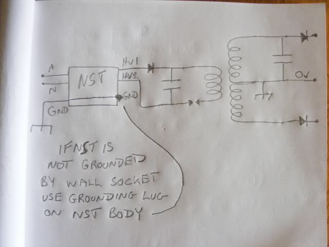
Hi Nolan, Can you try the circuit like this, and with the center tap grounded
as well ? Keep the tuning caps on the L2 as well. Are the tuning caps on L2
across both sides or across only one side to center tap ? I would put the
tuning cap across one side of L2 the positive side and tune using one side as
a coil so just forget about one side for the calculations, that will give two 1/4
wave sides to L2, if the resonance calculation is worked out using both sides
then the 1/4 wavelength will try to cover both sides of L2. I think we want
two 1/4 wave length resonators.
If that trips the Ground fault interrupter then just use one diode on one HV
side and the other side as the return I can draw a circuit if you want, no
probs.
P.S Here it is, this is the circuit I use so far with my small neon power supply,
this doesn't seem to trip the ground fault interrupter unless the spark gap is
made quite wide. I can take it to full power which is supposed to be 80 watts
but I only seen 65 watts leaving my battery to the inverter. Maybe it could
use 80 watts if powering a neon sign, dunno.
..
Hey Farmhand, The NST that I use is a 12v input / 4.5 k output, it does not have a center tap on the output coil that you can use. I have tried in many configurations to use both positive leads and spark to earth, but have not had any luck. I have removed the original circuit that powers the NST and I drive it with an H-bridge and signal generator.
I do have a 120v input NST but I have better results using the modified 12v NST. I am waiting on just a NST transformer from a manufacture that is unpotted so that I can use the center tap and we will see how that goes.
 Tweet
Tweet

 This was'nt a phantom charge cause the discharge went back slowly.
Comment