 Tweet
Tweet
Weight Loss...
Hello 4lpha1,
I am glad you see it, Thank You...
Definitively...a lighter Vehicle will drag much less, releasing stress to all power train system...acceleration times will become shorter, responsive take off will be excellent...it will fly...
Why do you think the Super Exotic Vehicles are so expensive?
Firms like Ferrari ...Lamborghini...Bugatti...Mc Laren...etc,etc
They are made with super light weight and five times stronger than steel composite materials...like KEVLAR, Carbon Fiber...Titanium, HSL Aluminum...Exotic Metal Alloys...etc,etc
Their Main Frames...their Uni-Body Structures...even the Brake Discs and Pads... are made with those Exotic and expensive light composites...check them out yourself...
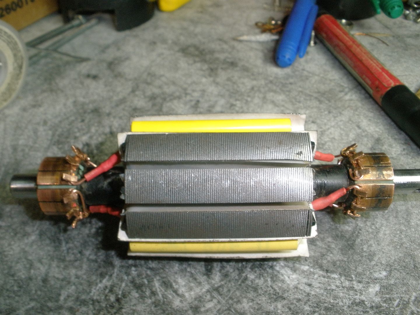
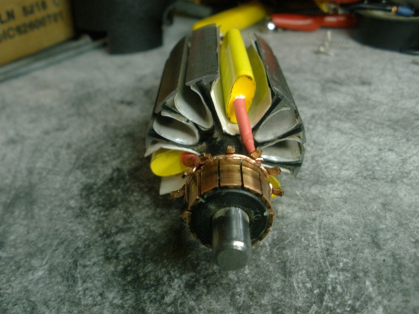
The good news are ...that we could also incorporate those exotic materials into our Motor Frames...
Wouldn't you like that your Car could fly off the ground?...and still be VERY Stable?
Stability at High Speeds is achieved by Air Space Dynamics Designs...Ailerons...Spoilers...Air Deflectors...and a whole world of Space Age Designs...
[IMG]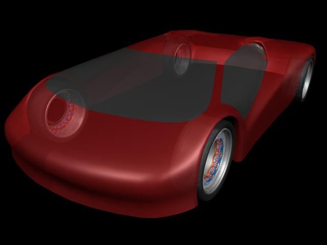 [/IMG]
[IMG]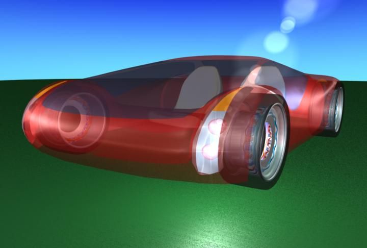 [/IMG]
Just to "tease" your desires...
You Will...be patient...
Regards
Ufopolitics
Originally posted by 4lpha1
View Post
I am glad you see it, Thank You...
Would weight loss really be a big issue though? With your motor design, it seems like a battery bank would need to be substantially smaller.
Why do you think the Super Exotic Vehicles are so expensive?
Firms like Ferrari ...Lamborghini...Bugatti...Mc Laren...etc,etc
They are made with super light weight and five times stronger than steel composite materials...like KEVLAR, Carbon Fiber...Titanium, HSL Aluminum...Exotic Metal Alloys...etc,etc
Their Main Frames...their Uni-Body Structures...even the Brake Discs and Pads... are made with those Exotic and expensive light composites...check them out yourself...
The good news are ...that we could also incorporate those exotic materials into our Motor Frames...
Wouldn't you like that your Car could fly off the ground?...and still be VERY Stable?
Stability at High Speeds is achieved by Air Space Dynamics Designs...Ailerons...Spoilers...Air Deflectors...and a whole world of Space Age Designs...
[IMG]
[/IMG][IMG]
[/IMG]Just to "tease" your desires...
God, I can't wait to actually start playing with these systems; I hate being in the dark.
Cheers!
Cole
Cheers!
Cole
You Will...be patient...
Regards
Ufopolitics
 [/IMG]


 [/IMG]

Comment