This forum is preserved as a permanent archive. The community continues at eMedia Press.

Announcement

Collapse
No announcement yet.

Bedini Ferris Wheel Regauging Motor

Collapse
X
 
  • Filter
  • Time
  • Show
Clear All
new posts

  • genessc
    replied
    Good question, This is one I'm curious to hear the answer to as well. How is this calculated or measured?

    Thanks for asking!


    Originally posted by nvisser View Post
    I have got a question.
    If we charge a cap of 16 000uF up to 42.5V and than discharge it to a 36v battery, how much energy in joules did we pass to the battery?
    Keep in mind that the cap only discharges to the same value as the battery voltage.
    Vissie

    Leave a comment:


  • nvisser
    replied
    Joules = (C . V^2)/2

    I have got a question.
    If we charge a cap of 16 000uF up to 42.5V and than discharge it to a 36v battery, how much energy in joules did we pass to the battery?
    Keep in mind that the cap only discharges to the same value as the battery voltage.
    Vissie

    Leave a comment:


  • John_K
    replied
    Bedini GT3

    Hi Mark P.,

    Good work. Do you have an analog ammeter so you can see the needle swing back and forth?

    Increasing the RPM will reduce the current draw as the amount of time the timing wheel magnet spends over the hall, so the coil will not be on for as long.

    As a test can you hold the rotor so the coil is on whilst you have the ammeter on the input and measure the draw current? Just long enough to get a measurement otherwise things will start heating up. Once you have that disconnect the coil from the circuit and briefly connect it to the battery and ammeter. You should get a similar draw current reading. This will tell you how well the circuit is switching.

    Only one of you LEDs is lighting. Have you checked the one that is not is not backwards or faulty? Also which way have you got the Zener connected? Can you post what voltage the cap is dumping at? When running mine at 36V my cap dumps at 42V about 3 times per second. I am using 2 x 6800uF 50V caps in parallel.

    I don't have my slave coils done yet as I'm waiting on some wire to wind them with.

    Keep playing with the timing, you should be able to get it to self start if you position the rotor about half way between magnets and give it a tap in the opposite direction. As soon as the hall fires it should kick the rotor magnet the other way and slowly come up to speed.

    @John B,

    Is there any chance that you could post a scope shot across the main coil? I would like to see your square wave and duty cycle. I think I ammmissing something and seeing the waveform will clear up what I think the duty cycle should look like. Thanks.


    John K.

    Originally posted by Rl2003 View Post
    John K. and Visse,

    I think I addressed both of these today. I put an amp meter on and I am below
    one half of a amp all the time now.
    I also did try some more cap sizes. The one that
    I feel is working the best now is a 25v 2200 uf. The led gets brighter and then
    discharges. It does this just over one time per revolution. The battery is charging now for sure.
    My RPM is back higher, but I may try to put a small
    load on the wheel just to slow it down some more.
    Here's a video of the latest cap change.

    YouTube - VIDEO0011.3gp

    Mark P.

    Quote:

    I did not test on 24V yet, but could I suggest that you insert an ammeter on the input supply and monitor that while adjusting the hall timing. If the dwell gets too long, meaning the hall is positioned in the middle of the round ceramic, the circuit can easily draw over 1A from 12V and that will heat up the transistors if you leave it like that.
    Vissie

    Leave a comment:


  • nvisser
    replied
    John gave the measurments in post 861
    The big coil =, if you tie all wires together 4.2 OHMS
    Outside coils #15 wire I have chosen 2000 feet = 6.368 Ohms each coil Can't Change that.
    1.82 Ohms Total all coils together
    .

    The idea of adding a winding to the main coil was to half its resistance . I only had one winding on it. I decided not to do it.
    Vissie

    Leave a comment:


  • Rl2003
    replied
    Originally posted by nvisser View Post
    I just inverted the polarities on my 2 slave coil so they atract. I also adjust the coils accordingly. It runs much better. Much better charging than before.
    Now after the latest info from John it looks like the slave coils should be double the resistance than all combined parallel wires of the main coil. For some reason I read it the other way round and have my slave coils half the resistance of the main coil. I will change it by winding an extra winding on my main coil to lower the resistance and see what the improvments are.
    Visser,
    I while back you posted this statement. Did you have any futher testing to
    show that this was a good idea?? I would like to keep progressing while the
    ball is rolling. My slaves are also half the master.
    And if one where to add a winding, what are we aiming for??

    Mark P.

    Leave a comment:


  • Rl2003
    replied
    Originally posted by John_Bedini View Post
    Mark P,
    Here is a link to the Bata tester some more current might help.
    Transistor DC Beta Function Tester Basic Design Oddmix Technology
    John B
    Thanks John,

    I will try this as well.

    Mark P.

    Leave a comment:


  • Rl2003
    replied
    GT3 Mini v2

    John K. and Visse,

    I think I addressed both of these today. I put an amp meter on and I am below
    one half of a amp all the time now.
    I also did try some more cap sizes. The one that
    I feel is working the best now is a 25v 2200 uf. The led gets brighter and then
    discharges. It does this just over one time per revolution. The battery is charging now for sure.
    My RPM is back higher, but I may try to put a small
    load on the wheel just to slow it down some more.
    Here's a video of the latest cap change.

    YouTube - VIDEO0011.3gp

    Mark P.

    Quote:

    I did not test on 24V yet, but could I suggest that you insert an ammeter on the input supply and monitor that while adjusting the hall timing. If the dwell gets too long, meaning the hall is positioned in the middle of the round ceramic, the circuit can easily draw over 1A from 12V and that will heat up the transistors if you leave it like that.
    Vissie

    Originally posted by John_K View Post
    Hi Mark P.,

    Nice video, thanks for sharing.

    I was able to get the RPM down by increasing the gap between the coils and the rotor magnets.

    If the cap is not dumping and you are using the SCR/Zener/LED method it could mean that gate voltage is not high enough to trigger the SCR. But if that is the case it doesn't explain why the battery is charging.

    Great looking setup!


    John K.

    Leave a comment:


  • John_Bedini
    replied
    Bedini GT3

    Mark P,
    Here is a link to the Bata tester some more current might help.
    Transistor DC Beta Function Tester Basic Design Oddmix Technology
    John B

    Leave a comment:


  • Rl2003
    replied
    Originally posted by John_Bedini View Post
    Yes, That circuit will work If you want to adjust a set level then put a 100k pot where the 20 k is and a 10K back to the positive of the battery is. Then you can set for each transistor. Make a box to do this and mark the dial. do reverse for NPN. That circuit is correct.
    John B
    This is what I did to match the transistors beta.
    I just switch the pos. and neg. from the power supply in the banana jacks, reversed the amp. meter, and was able to test the PNP's and NPN's with the
    same little set-up.
    Here's two short videos.
    YouTube - VIDEO0009.3gp

    YouTube - VIDEO0010.3gp

    Mark P.
    Last edited by Rl2003; 01-26-2011, 04:36 AM.

    Leave a comment:


  • John_Bedini
    replied
    Bedini GT3

    Cody,
    Yes that is right, I will find out where to get barium titanate I think That Bob Lazar at.
    United Nuclear , Scientific Equipment & Supplies. Might have the chemicals to do this. I want to run the SG 3
    On this energy. I will start with a miniature first.
    I will see if or where my lab notes are on this. I must search through 10 different outboard drives.
    Thanks for posting this work.
    John B

    Leave a comment:


  • cody
    replied
    John,

    Happy to share what i got. I made numerous small scale test cells starting off by probing rocks for voltage and then later finding the important ingredient seemed to be the silica, i moved on to sodium silicate and silica gel, as well as perlite. I was heating them and applying HV DC. All my testing lead me to believe that it was really just a galvanic reaction taking place due to silica's desiccant properties, so the best output, from my opinion, was from the water in the material and the dissimilar metal electrodes. Having said that, i still see the possibility for the crystal diode explanation since its putting out DC.

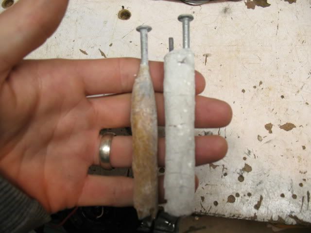
    Here are some of my silica test cells. The one on the left is pure sodium silicate that i soaked a paper towel with and wrapped up a zinc coated nail and graphite from a carpenters pencil. This was heated and let to dry. The paper towel really helped keep this thing staying together over time, you can see the other cell is cracking. The next is sodium silicate mixed with crushed silica gel beads that was heated and put in a pvc tube to dry with the electrodes in it and then removed.


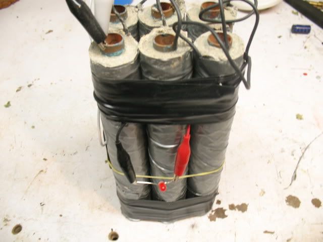
    Once i was convinced that the effect i was seeing was really from acidic water (H20+CO2)and dissimilar metals, i moved on to a different approach. Trying to take advantage of desiccants for a maintenance free water cell. I moved on to a concrete morter mix(which of course has silica in it) mixed with water and calcium chloride. I forget the exact proportion i settled on, i think its in my notes somewhere. Either way, that is the cell below which has been running the LED for just over a year now. The output is not that strong but it is continuous so far. Not sure if the calcium chloride is consumed over time, im no chemist, so it may not be necessary. The electrodes are copper and aluminum. You can see the copper is starting to corrode, this is why i prefer graphite as well as your pyrite idea.


    I remember reading about your quartz and rhodium experiments somewhere and would love to hear about them. Im pretty sure John H is using a barium titanate mix which i think would work for an elecrtet type "battery", but i have yet to get my hands on that material to test it.

    Cody

    Leave a comment:


  • John_Bedini
    replied
    Bedini GT3

    MK1,
    I have wound all the coils the same way.
    John B

    Leave a comment:


  • mk1
    replied
    Originally posted by John_Bedini View Post
    John K
    Motor running on Iron Pyrite Battery New setup.
    YouTube - Iron-Less Monopole Motor Runs On updated Iron Pyrite Battery 2
    John B
    Great video ! I have had a great time looking at all you videos , i find it interesting to see how square the wave of iron is .

    I was also wondering if you could tell me if both coils the copper and the iron one wound the same way from what i can see the iron is clockwise top going , is the copper one the same ?

    I hope you could answer , i know this seems less important to most but not to me .

    Thanks in advance !

    Mark

    Leave a comment:


  • John_Bedini
    replied
    Bedini GT3

    Cody,
    The problem with dry rock batteries is that you need Rhodium electrodes. I found this out experimenting. I asked Tom Bearden if he ever spoke to John Hutchison and He said no about that battery. Yes Water Glass works just fine if I doped it, which John H is not going to say.
    (Government Surplus Crystal Rhodium coated Quartz Discs )

    I have been grinding different rocks to make semiconductors for 30 years I have seen many different things. I will see what I can get working in a dry battery and post the information. John Hutchison will never tell you anything but I know that you can do it with the right electrodes. Cooking the mix is the important part as it forms bubbles where the energy collects around electrodes. I'm not quit sure that it is an electret , more like a solid state battery ( crystal lattice battery) (Casimir effect) ("Tesla also did this"). Hope you post some information on how you made the cell as I'm going to do that too.

    John K The Magnesium roll is under the paper towel

    Thanks for posting this information as it seems to be a whole new field in low energy powered devices. The next question that I'm looking into is very low powered Hall devices .7 to 1volt . So far I think I have located one from RHOM Electronics. They make some low power stuff. Each one of these batteries have a different waves on that motor which I'm storing in the digital scope.

    SCOPE
    Some ask what the scope is, it's a B&K 2542 DSO LCD Color.
    Thanks
    John B
    Last edited by John_Bedini; 01-25-2011, 08:23 PM.

    Leave a comment:


  • genessc
    replied
    Hi John K, Mark P,

    Most likely the reason the battery is charging is because the capacitor selected is to BIG and its not able to fully dump the charge before the next incoming magnet comes in to recharge the collector cap. Try using a cap half that size and see if that resolves the "constant on" state of the SCR.

    SCR's are iffy this way. If the unidirectional pulse of current from the collector cap doesn't end before the next incoming charge pulse thats depositing energy into the cap hits it, the SCR will just keep on conducting. Saw this on a 15hp RV discharge circuit I tried to rig up... had this same problem... only in that case I fixed it by changing the load to something that lets the pulse more quickly fire and end. (a lower impedance load)

    Anyways thats likely the issue.
    Gene

    Originally posted by John_K View Post
    Hi Mark P.,

    Nice video, thanks for sharing.

    I was able to get the RPM down by increasing the gap between the coils and the rotor magnets.

    If the cap is not dumping and you are using the SCR/Zener/LED method it could mean that gate voltage is not high enough to trigger the SCR. But if that is the case it doesn't explain why the battery is charging.

    Great looking setup!


    John K.

    Leave a comment:

Working...
X