
Ok, I've finally made a video that I said I would. I just had a little trouble with
my video recorder, so I am using my phone for now. It's short because it takes
forever to upload a larger file.
I did flip the two led's and to the opposite direction and this worked. But only
one blinks, and only when the cap is not in the circut. I am letting it run for a
couple hours to see what heppens to the sec. battery. It was almost dead...
My transisitors are getting hot and I am in the process of matching some.
I have been looking on the internet on how to do this, as I have never matched
the Beta of transistors before. If any one can introduce me to a simple way to
do this I would be thankful, other wise I will make a test circuit to do this.
YouTube - VIDEO0008.3gp
Mark P.
-
Hi John K and David.
I got my device up and running last night. Its built using what I have laying around so its not up to 3gt spec. But it is the half circuit, triggered by a hall. Im running on 24v, 200-300ma, 8 pole rotor 500mm in diameter.
Coil is 6 filar, each strand 0.9mm @ 2.1ohms per strand. I presently have it running with 4 strands in parallel. I had some heat in my circuit, particularly the PNP and I got rid of most of it by adding a rheostat off the 220 ohms which was discussed before. Even with the rheostat at its lowest setting (effectively adding very little if any resistance) the heat generated is considerably less, barely warm to the touch now. Tweaking this resistance lowers the input current even more. Not that there is much current here when its up to speed anyway.
Charges a 2200uF cap up pretty fast, still have to build the discharge circuit.
Took a little time to get the hall in the right place. I couldnt figure out why it would work then get slower and slower and eventually stop. I eventually found that there was a spacer missing, so the timing disc on the shaft would slowly get further and further away from the hall, eventually switching off altogether. When I have made up the spacer for it I will post a vid.
RegardsAttached FilesLeave a comment:
-
-
Bedini Cole Switch Problems.
John K,
Thanks for that, I was starting to pull my hair out, I thought I tried everything save starting again.
Well saying that I am going to start again and start matching MJ's and testing different Base resistors.
Thanks Again.
Regards,
David Brown (Belfast)
Originally posted by John_K View PostLeave a comment:
-
Bedini 3GT
Hi David,
If one transistor is getting hotter than the other then they are not matched. This means that one transistor is switching on before the other and yaking more of the load than its partner. See if you can get a pair with the same Beta. I use my meter on diode test mode and go for no more than 2% difference.
You could also try and replace the 470 ohm resistors with a higher value. The duty cycle will depend on the dwell for the hall so if you don't see 50% then adjust the dwell.
As John B suggested you can parallel the transistors. Also research how to connect Sziklai pairs.
I am still waiting for some ATS137 halls to arrive as I blew what I had and John B has suggested that the ATS137 works very well.
I hope this helps.

John K.
Originally posted by david.brown View PostLeave a comment:
-
Bedini Cole Switch Problems.
John K,
I think I am having the same problem with running the Bedini/Cole Switch (B/CS) at 24v as you are.
The MJL21193 is hotter than the MJL21194 and after 5-10mins of run time the B/CS it pretty hot, I have an Oscilloscope and I can see between the Emitter & the Collector of the MJL21193 and is not giving me a nice 50% duty cycle.
I have tried changing the resistance of the resistors that feeds and discharges away from the base of the MPSA056 but it still is not switching right.
I was kind of hoping you have had some joy with your B/CS and could point me in the right direction.
Regards,
David Brown (Belfast)
Leave a comment:
-
And, by the way, this is an EXCELLENT way to increase the radiant energy directed to the charging battery in a regular SSG setup. I'm currently triggering via hall on my 3PM. I've ditched the pot, or any trigger resistance, for that matter. Using an opposing magnet behind the hall is the best way to influence everything. You will find, that for any given current draw, you can really boost the radiant charge by using this method, as opposed to trigger resistance.
Jason S.
Originally posted by nvisser View PostLeave a comment:
-
Vibreedo Coil
Ecoman11, thanks for your simplified explanation for the Vibreedo coil here. Over
in your other thread I could never figure out what you were trying to do. It now makes sense. Maybe it was just me not getting it.
FRCLeave a comment:
-
Minoly,
I've done quite a bit of experiments and can tell you that the second magnet is only increasing or decreasing the field in the electromagnetic coil (for small setups like the one you posted). You can test this by putting second magnet on the opposite side of the coil and flip the poles to speed it up or slow it down. All this does is increase or decrease the current.
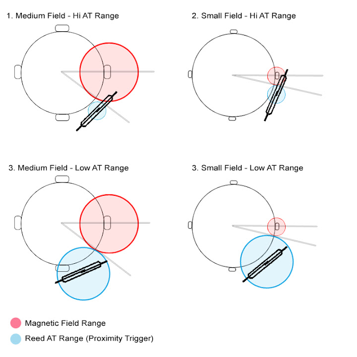
With a simple reed motor, the duty cycle is produced two ways: the motor speed (variable); and the magnetic field + reed's proximity (fixed). The image below shows a detailed diagram of how a reed switch is triggered. Here we can visualize the on/off time by looking at the red zone passing through the blue zone. #2 would be the shortest on/off time while #3 would be the longest. You can also see how the reed's angel position changes according to where the magnetic field and proximity range meet. This is very detailed tuning and tedious work but when it's setup right will use less current by the milliseconds per pulse.
JB,
Like transistors, a reeds quality will make a difference in the waveform and produce a better spike. I mostly use Hamlin DRR-129 ($3-4) and buy various AT ranges (10~20, 30~40, 80~100, ect.) depending on what size magnets I'm using. For small applications like the iron coil I would suggest trying 10~20 or 20~40 range. For large applications with big neos I use Meder KSK-1A83 (100~120) tungsten tip reeds. These aren't cheap and should only be used for final projects. You can find the Hamlin reeds at Digi-Key and the Meder reeds at Master Distributors (none in stock at the moment).
Now about that ringing waveform. This might be an effect that I and another experimenter by the name of Ossie Callahan came across. That may be your reed switch fluttering in what I call the diffusion zone. I posted a thread on this effect a while back found here. http://www.energeticforum.com/renewa...eedo-coil.html The diagram shows a small diffusion area near the coil but it can extend out a few inches.
There are certain zones around a coil where the magnetic field, current and reed contacts all interact and cause the reed to flutter. This chops up the pulse as shown in the image below from one of Ossie's paperwork. If you turn the rotor very very very slowly by hand you may hit a point where the reed starts to flutter while the rotor is still. I could be mistaken about your setup but I've produced similar waveforms this way.
The trick to getting rid of the arc in the reed is to put the diode right on the lead of the reed switch. If you try the circuit show in that link you will have no arc appear and the full spike going to the battery or cap.
Lastly, as I mentioned before, my interest is in physical switches so here's a little experiment for anyone.
This experiment works best with small round tungsten carbide rods.
Replace your reed with two leads connected to two small steel files or cobalt drill bits. Tap them together quickly but firmly and you'll see your neon light with barely any movement on your amp meter. There is a lag time in the current and it can be controlled by precisely timing each tap. It's not a practical switching method but it does go to show that we need to experiment with different materials rather then the standard.
P.S. JB, Ever wonder why those Neve 1073 pre-amps sounded so good? Makes you wonder what Rupert Neve was winding those transformers with.
EcomanAttached FilesLast edited by Ecoman11; 01-23-2011, 07:40 AM.Leave a comment:
-
-
GT3 Mini v2
John,Originally posted by John_Bedini View Post
I believe we have contact..It's late and I fading fast. I had a connection flipped
and I just spotted it after your suggestions led me to start swaping wires.
She's running and with all three coils, in parallel. I got it to slow down a bit
after adj. the timming. I need to make a slight mod. to the bracket holding the
hall but I think that will do it for now.
Thanks, Out for now.
Mark P.Leave a comment:
-
GT3 Mini v2
I also made a slight miss calculation when designing the timing wheel.
The magnets are about 1/16 to far apart than what I wanted. You can
see it in the pictures. I did it in Auto Cad but I was still off and the
magnets are 12mm in dia. and not 1/2 inch.
I have to make a new one, maybe that will help a little...
Mark P.Leave a comment:
-
GT3 Mini v2
Yes, I thought that maybe an option. I have an extra winding on the slave coilsOriginally posted by John_Bedini View Post
that I will try in series, and I also have two other coils with Quad filar I could
try two wires in seris and then three and four if we need. I just need to trim
the plexi base off some so it will fit under the magnets.
Mark P.Leave a comment:
-
Bedini GT3
Mark P,
I would really like to try a series arrangement on those two coils we want them to push delayed, It will do that I'm sure. Put them is series and lets see before we do anything else.
John BLeave a comment:
-
GT3 Mini v2
Also I recorded this on video but when I transfered it to my PC I
didn't get any sound with it. I will try again tomorrow for all you
who are wanting to see it running.
Mark P.Leave a comment:
-
John,
What ever it takes to get it working. Well almost anything.
As you know it took some time to build, but I will say well worth the time
spent. I enjoy working on this with everyone, and I am sure we will get it right.
The slave coil measured at 1.2 ohms and .8 ohms in parallel together.(#18awg)
The main coil is at 2.2 ohms on each (#18awg) separately and 1.3 in parallel.
The two # 21 wires are at 4.2 ohms each if that is at all relevant right now.
Do I need to raise the resistance? Would #21awg be better?
The slave with #21 awg 165 ft is 2.3 ohms, but I can put
more wire on it than that. We need to raise the Impedance?
Mark P.
Originally posted by John_Bedini View PostLeave a comment:
Leave a comment: