

-
Hi all
I wonder if this video is not also relevant in this thread ?
generador Figuera approach 3 - YouTube
Hi Mr Clean
bravo for your work, go on man
good luck at all
LaurentzLeave a comment:
-
new vid
my numbers could be a bit +or-, but 2.4 watts DC in as shown in last vid...and the 5 watt resistors were getting HOT... whatever that insinuates...
and regardless of it not being rms, the overall measurements will clearly show themselves, and input vs output was always looking good
7.3v max peak across 10 ohms = 5.32watts
23.5v max peak across 100 ohms = 5.52watts
= consistent = accurate
100 ohm loaded secondary
primary reading across 1 ohm input resistor 2.89v
10 ohm loaded secondary
primary reading across 1 ohm input resistor 1.5v
=2.25watts
open unloaded primary 3.5v
i believe those are good numbers, and based on those digital readings being so closely agreeing, and i feel i can still look at it as 12vdc at .2 amps...
....making the 5 watt resistors HOT...
39H Don Smith Device Project:BiToroid Purely Resistive Loads, Examining Input and Output Waveforms - YouTube
and looking closer at the circuit in my posted schematic, the ammeter is directly off the positive from battery/12v source, and you can find the exact circuit i used on
DIY Homemade Ignition Coil Driver - RMCybernetics
and 9v PWM as controler
DIY Homemade Signal Generator with Pulse Width Modulation - RMCyberneticsLast edited by mr.clean; 11-15-2012, 05:43 AM.Leave a comment:
-
@ekpod.
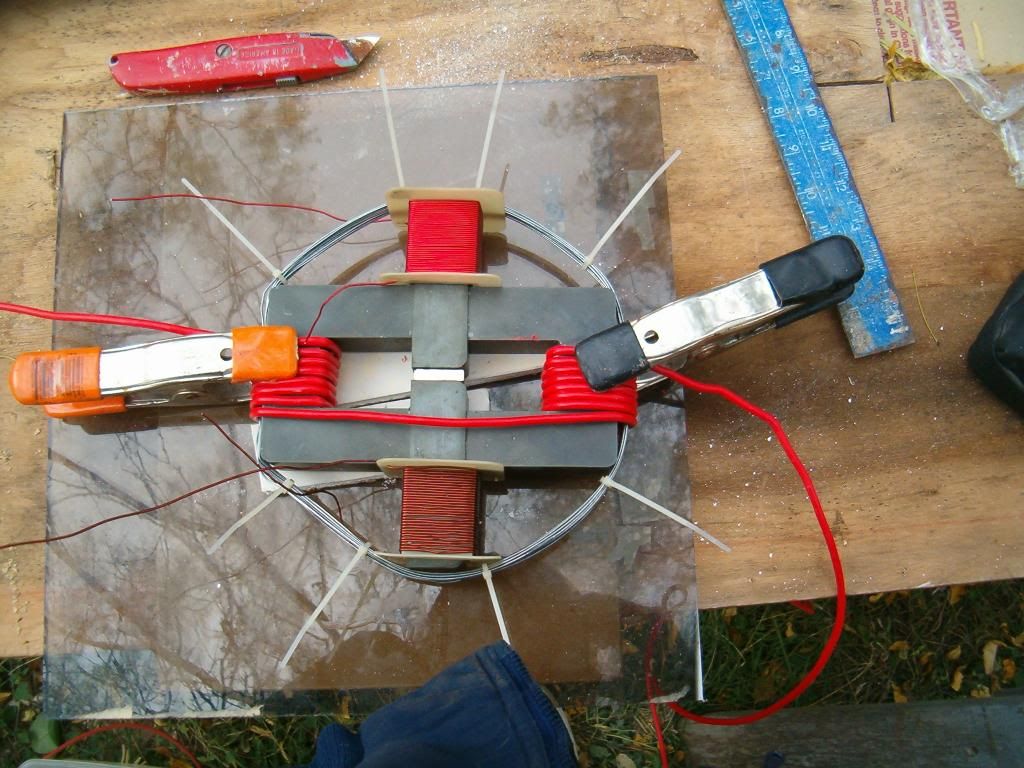
You can do the same with the air gaps in the setup from my picture as well.
Basically, the center part with those air gaps [|] is
Clemente Figueras' configuration, but in his case there are two primaries on the sides and a secondary in the middle. Primaries create magnetic flux unidirectionally and the flux from each side corresponds to the induction of current in the secondary output coil in one direction only. Splitting the cycle in two halves allows the mirror "C" core part to become alternate path for the CEMF flux from the output to take a route through that core (which is not magnetized at the moment of maximum saturation with flux from the other primary). Now, I Get IT!
So we do not need those extra core pieces to achieve that effect!Leave a comment:
-
This is what I propose: a configuration based on four 'C' (or 'U') type cores and one 'I' matching type.

Those are not too hard to get nice and square ferrite cores, flat surface, great for configs like this!Leave a comment:
-
Bi-Toroid Variant
It looks very well constructed Berg, Verpies, Mr.Clean. Decoupling the primary core from each secondary core is what the following is designed to accomplish. The air gap will naturally increase reluctance to the primary. The secondary cores must be allowed to interact with much less resistance to the flow of magnetism.
 Last edited by ekpod; 11-14-2012, 10:05 AM.
Leave a comment:
-
Schematic of mr.clean's design
Thanks for the schematic, verpies.Originally posted by verpies View Post
Click here to download the schematic.Leave a comment:
-
Thane's Explanation of the BiTT
Here's a video link that is still active at this time.Originally posted by vidbid View Post
FREE ENERGY # 35 BI-TOROID TRANSFORMER - 377 % OVER UNITY MOTIONLESS - YouTube
I suggest you download a copy of this video before it's removed.
By the way, here's a video by woopyjump. I suggest watching it to gain more understanding: bitt power factor 2 .wmv - YouTubeLeave a comment:



Leave a comment: