-
I just don't understand why if someone was trying to make a very efficient transformer they would want to add air gaps at all. My understanding of the principal is thicker core equals less reluctance just as thicker wire equals less resistance. -
Hi pmazz850,
My understanding on magnetic circuits is that reluctance can be controlled by introducing air gaps with controlled gap sizes i.e. the higher the distance between the facing surface areas the higher the reluctance is. And it makes very little difference when you have a core with a permeability of 100,000 and you make a certain airgap in it and then you have a core with a permeability of 5000 and you introduce the same size air gap: the result is pretty much the same from reluctance point of view (provided the core sizes mechaniclly are much the same for the two cases).
So I do not think you have a drawback right now with not having two cores with much differing permeabilities, you can control rluctance by cleverly choosing air gap distances. Unfortunately you have to be precise to at least 1/10 or 1/5 mm in controlling the gap and the facing surface areas would better be smooth, ideally. Nonmagnetic spacers can be chosen in advance with some thicknesses to keep up with gap control.
GyulaLeave a comment:
-
So i had an idea for a bitt. I have a laminated core from a 3 phase transformer. The three legs of the core are equal size. I was thinking of splitting some laminations off and shifting them over so that the first leg would now be narrower and the second two would be the same size as they were to start. The extra would just hang over, unless i cut them off entirely.
Being its a 3ph transformer having equal size legs the laminations can just be shifted. But does it really have to be a 10:1 reluctance ratio? I'm not sure how much power you can pull from a core that size. If i made it 10:1 the primary leg would be 5mm x 30mm. Compared to 30mm x 50mm. I don't really want to build it for mW power. The size of the core is pretty decent(150mm x 50mm). Should be able to make some usable power. Any advice on this idea?Leave a comment:
-
An iron ring has some very interesting quality's watch the iron ring he uses for a barrier to separate 300,000 volts.
300Kv On A Television - YouTubeLeave a comment:
-
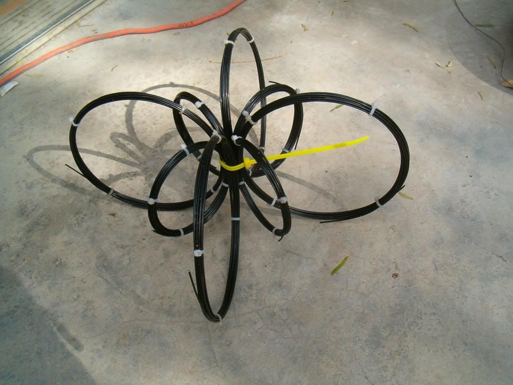
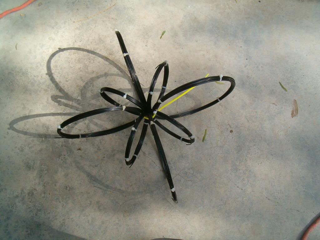
This resonator is built out of 16 ga. bailing wire its just a mock up, still have to secure wire ends then start winding the coils.
Center primary and four secondary's on the larger bands, the smaller bands are to shunt the primary.
Leave a comment:
-
Hi everyone and thanks, but credit goes ThaneOriginally posted by ekpod View Post
Excellent catch, lol yes it is pretty much extra primary legs rather than sec core legs, BUT keep in mind i snapped the ferrites and they re connect almost flawlessly, BUT you are still correct, the sec cores need to be more secluded from primary, mine saturates too easily.
I was even thinking higher perm metglass core material as well, just on outer ring, with no connection to primary at all, and primary having lower perm ferrite would have even less reason to fight primary emfLeave a comment:
-
Hello Mr.Clean,
In going with the diagrams posted of your transformer system, thus far you have not demonstrated the Bi-Toroid core configuration as developed by T.Heins.
The precise reason it is not operating as such is due to the secondary decoupling cores residing at the same magnetic reluctance as the primary cores. Magnetically they are one and the same.
Whereas in a BiTT configuration the primary core reluctance is much less than the secondary decoupling cores, your transformer diagram shows them with equal reluctance due to the positionings of the air gaps.
...

Leave a comment:
-
Yes. Thanks so much Kurt? Is it? I can hardly wait for your scale up!Leave a comment:
-
Good job, thank you for your persistence and willingness to share, shows your true character.
I think alot of us are working towards an end now, this gives us a direction thanks to your efferts.
dave
edit: forgot to add a link Back to Basics: Tutorial on LC Resonant Circuits - YouTube
viva le revolutionLast edited by Dave45; 11-20-2012, 09:46 PM.Leave a comment:
-
new vid, solid overunity?
hi everyone, back with some more measurements and testing.
i noticed my scope has a built in RMS calculator with internal calculable ohms.
it is not simply reading peak spikes, the scope understands that peak voltage is NOT the same as wattage, and it is a function that leaves nowhere to hide...
with all factors the same, using sine wave, and low frequency, the power thru the bulbs is the only variable.
and you will notice the readings are visually consistent with the apparent behaviour of the bulbs.
i am confident now with the RMS readings shown here. and the results here are in line with the inventors claims
now to scale up, and use this system as a HV resonant driver for my Smith coil board, or simply go with this system entirely, we'll see
here is what im confidently calling, overunity with the BiToroid, inspired by the people who originally disputed the output readings
Now with these RMS readings i am further convinced of the potential in this system
40 Don Smith Device Project: BiToroid SineWave Testing, Confirming RMS in/out - YouTubeLeave a comment:
-
Image shack seems to be down at the moment.Originally posted by Berg View Post
It's the strangest thing, so I re-uploaded to Image shack.

and below are some images of the Bill Muller configuration for reference purposes.
The Stator:

and the Rotor:
 Last edited by Berg; 11-20-2012, 09:26 AM.
Leave a comment:
-
New Use of BITT for a Generator on a Bill Muller Disc
Overhead View:

New design for a generator incorporating BITT stator coils.
You could also have more rotor magnets to stator slots so there would be less cogging.Leave a comment:
-
if the secondary's draw energy like I think they will I dont think we could run the system at peak resonance once the lc series goes into short circuit mode the energy is phenomenalLeave a comment:

Leave a comment: