If this is your first visit, be sure to
check out the FAQ by clicking the
link above. You may have to register
before you can post: click the register link above to proceed. To start viewing messages,
select the forum that you want to visit from the selection below.
Ekpod: " Finely illustrated Dave45 ... This interesting arrangement of primary coils ... may indeed have the quality of harvesting bEMF from energy throughput to the secondary, reducing the wattage used in accordance with the magnetic properties of each component combined in resonance. "
Electricity and magnetism cannot be separated in nature because one is a reaction of the other.
With current moving through a wire we have a magnetic field orbiting the wire
With an inductor the fields trade places we have an electric field orbiting the magnetic field.
We are trying to catch the electric field not the magnetic field, the magnetic field is compressed space, check out z pinch.
We have two advantages the magnetic field can be manipulated with iron and the electric field can be manipulated with copper.
When a coil is energized it compreses space this causes a low density in the aether the aether is electric in nature and seeks balance so is drawn to the coil.
If we could isolate a coil from the aether it would never find balance and would continually draw the aether, we can do this using iron.
This vid shows how, Iv posted it here before but Im putting it back up because it is very important it shows us how to isolate a coil from the aether. 300Kv On A Television - YouTube
The iron ring sets up a magnetic field that the electric field cannot cross unless there is a conductive path to pass through.
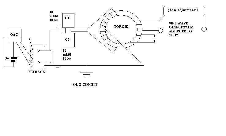
Since the electric field cannot pass through the toroid without a conductive path it orbits the toroid like this
Energy can transfer between the primary and secondary, it is this field that transfer's energy not the magnetic field. But when the field is pulsed the primary is still not isolated so some energy collapses back into the primary,
we have to use more rings to isolate the primary totally from the aether.
When the primary is totally isolated by the magnetic rings the electric field cannot collapse into the primary but will enter a resonant secondary or multiple resonant secondary's, but the primary is never quenched.
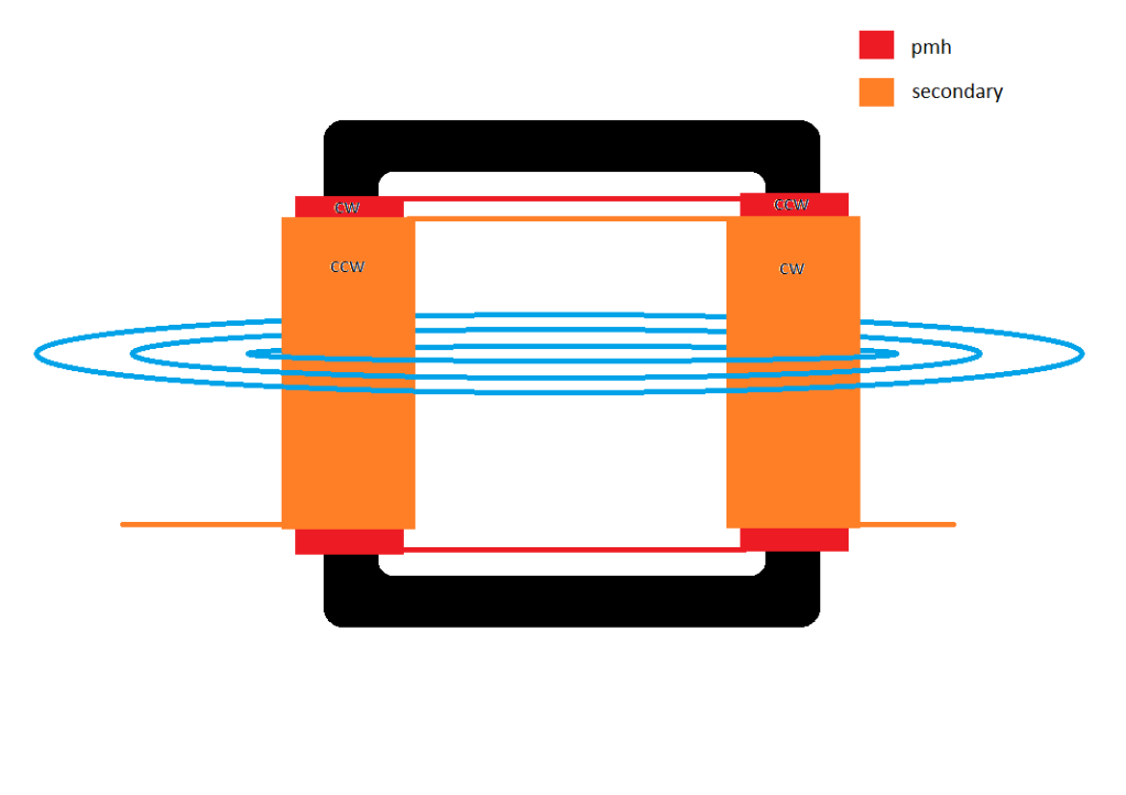
Will be interesting to see your results, if we look at the pmh it requires a soft iron core for a continuous magnetic flow but if you want to route bemf a ferrite core would seem to be a better option since it needs to die away.
I really dont think you have to reroute bemf if you use two primary windings side by side cw and ccw the bemf from one primary reinforces the opposite primary and vise versa.
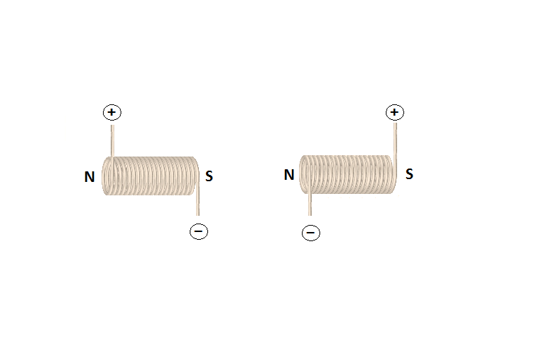
If you put two coils together that have the right pole orientation you create one magnetic field but now you have two coils to pulse that field.
In the other thread (Donald Smith) http://www.energeticforum.com/renewa...tml#post216045
I described that you connected your probe in series with (and not across) the 10 Ohm load resistor and that was the reason you measured 9.28V, please understand it. In this series situation the current was 9.28uA only which actually loaded the secondary coil.
What you are showing in your latest video (42 BiToroid:Improvements..) I also disagree with in that you measure across the LEDs and you make the scope believe its probe is across a 8 Ohm load (at 2:40) but eventually the 4 Ohm got selected and the scope then shows 3.13W4Ω, do you really believe you have had 3.13W power across the LED???
The Velleman Support clearly wrote on their forum that for audio power measurements you have to use an appropiately rated power resistor in the range of 2Ω, 4Ω, 8Ω, 16Ω & 32Ω and then select the correct value in the Menu to see the power across it. Your LEDs did not represent either a 8 or a 4 Ohm load for sure.
A LED is a diode it has a forward and a reverse direction and a white LED when brightly lit may consume 20mA at 3.2V forward voltage, this is 64mW.
There is another "issue" with LEDs when you use them in AC circuits: they can conduct and let current flow when the AC voltage across them is just higher than their forward voltage, and if you consider an AC sine wave with 4V peak to peak amplitude then a white LED will conduct only in the moments when the AC amplitude just reached approximately 3V (in the diode's forward voltage direction) and higher, so current will flow via this LED when the AC peak voltage, coming from a zero crossing, sweeps (exceeds) 3V to 4V and back to 3V, ok? If you compare the time lenght of this LED ON time when it brightly lit to that of the full AC wave time period (1/f) you will see that this ON time is only about 1/4 part of the full wavetime. In case of a resistor the ON time is 100% versus LED's ON time of 25% in this situation.
I hope you digest and understand these.
Gyula
hehe i know there is not 3 watts in the LEDs,
my point was the range that i needed to zoom into in order to read it, it saw the input in the mW range and the output in the W range.
if i could replicate the resistance of the LED (if possible) it would be interesting ..maybe
i dont see how it could be more clear, the 9.28v was measured just like you would measure voltage in primary, while the resistor was in place i measured volts across end of secondary around to the beginning of the resistor
i couldve sworn that Gyula said that there are 2 places to measure secondary, across supply with resistor in-line, and then across resistor?
Hi mr.clean,
In the other thread (Donald Smith) http://www.energeticforum.com/renewa...tml#post216045
I described that you connected your probe in series with (and not across) the 10 Ohm load resistor and that was the reason you measured 9.28V, please understand it. In this series situation the current was 9.28uA only which actually loaded the secondary coil.
What you are showing in your latest video (42 BiToroid:Improvements..) I also disagree with in that you measure across the LEDs and you make the scope believe its probe is across a 8 Ohm load (at 2:40) but eventually the 4 Ohm got selected and the scope then shows 3.13W4Ω, do you really believe you have had 3.13W power across the LED???
The Velleman Support clearly wrote on their forum that for audio power measurements you have to use an appropiately rated power resistor in the range of 2Ω, 4Ω, 8Ω, 16Ω & 32Ω and then select the correct value in the Menu to see the power across it. Your LEDs did not represent either a 8 or a 4 Ohm load for sure.
A LED is a diode it has a forward and a reverse direction and a white LED when brightly lit may consume 20mA at 3.2V forward voltage, this is 64mW.
There is another "issue" with LEDs when you use them in AC circuits: they can conduct and let current flow when the AC voltage across them is just higher than their forward voltage, and if you consider an AC sine wave with 4V peak to peak amplitude then a white LED will conduct only in the moments when the AC amplitude just reached approximately 3V (in the diode's forward voltage direction) and higher, so current will flow via this LED when the AC peak voltage, coming from a zero crossing, sweeps (exceeds) 3V to 4V and back to 3V, ok? If you compare the time lenght of this LED ON time when it brightly lit to that of the full AC wave time period (1/f) you will see that this ON time is only about 1/4 part of the full wavetime. In case of a resistor the ON time is 100% versus LED's ON time of 25% in this situation.
I hope you digest and understand these.
Hi Mr Clean, Anyway all things considered, for a whipped up experimental set up the efficiency
is pretty good, and is probably a bit better than measured. You might want to
consider using some 0.5 Watt purely resistive resistors I'm not sure but I think
the ones you used in the last video's were wire wound and have inductance.
I think one way is to keep the primary current sensing resistor a low resistance.
value to minimize heat there and size the load resistor to be about the
resistance of an intended load, to my way of thinking that makes sense, the
values you used were good though.
Keep on truckin my friend, nothing ventured nothing gained. You would need
to make a lot of mistakes to exceed my list of boo boos.
Cheers
P.S. I think in Thanes demo's he used a 2 K load resistor to keep the voltage
up, or was it a 1 K resistor. Anyway 1 KOhm I think is an unrealistic load
resistance. The power dissipated by the primary current sensing resistor
should be considered as output because that heat would not be created were
it not there for measurement.
Hi Mr Clean, The main thing is to understand why the measurements are made
that way. You deserve respect for sticking with it, I mean no disrespect, I'm
no expert myself. With resonance on the primary the phase difference
between primary voltage and current will be close to zero so apparent input
power will pretty much equal real input power. As the others say though it
should not be taken for granted. With the phase difference at 90 degree's the
power factor would be zero, however just lining up the the wave forms by eye
on the scope like Thane did is not satisfactory, I don't think a stable power
factor of 0.00 or (a stable phase difference of 90 degrees) between the
primary voltage and current is possible with a load being powered from the
secondary. What I see is the phase angle is constantly varying to slightly
either side of 90 degrees, and during the phase deviations from 90 degrees
energy is input to the secondary.
When talking such low power levels as shown by Thane with the BiTT demos
only a very slight momentary variation in phase would deliver the power levels
seen.
Someone should ask Thane for another demo with the input measured from the
wall socket with a kilo watt meter and the phase angle computed by a good
scope in real time and with output power at least 1 Watt. I have a suspicion
that if that happened the 8000% OU would turn into about 60% efficiency.
A very small deviation from a phase angle of 90 degrees make a big difference
to the power factor.
eg. Phase angle 90 degrees cos(90) =0, cos(88) =0.034. If the apparent input
power was 1 Watt then the power factor 0.00 means no real input and a
power factor of 0.88 means 1 Watt x 0.034 = 0.034 Watts input.
So we can see any small deviation from 90 degrees phase difference will
cause real input power. My contention is that phase angle do not remain
completely stable. A snapshot of 90 degrees phase angle for a single moment
in time is not accurate.
Hi Mr Clean, For the output, the voltage across the load resistor is the voltage to multiply the
current by. If the 10 Ohm resistor is the only load across the secondary then
you measure the voltage across the 10 Ohms 0.563, divide by the resistance
10 ohms to get 0.0563 then multiply that by the voltage across the load resistor 0.563 = 31 mW.
Where exactly did you measure the 9.28 volts at ? Is the resistor the only load.
You didn't show where you connected the probe to measure the 9.28 volts. If
the 10 Ohm resistor is the only load on the secondary then your output is about 31 mW.
Input looks to be about 40 mW. That is assuming the 10 Ohm load resistor is the
only load on the secondary measured.
Cheers
i dont see how it could be more clear, the 9.28v was measured just like you would measure voltage in primary, while the resistor was in place i measured volts across end of secondary around to the beginning of the resistor
i couldve sworn that Gyula said that there are 2 places to measure secondary, across supply with resistor in-line, and then across resistor?
Hi Mr Clean, For the output, the voltage across the load resistor is the voltage to multiply the
current by. If the 10 Ohm resistor is the only load across the secondary then
you measure the voltage across the 10 Ohms 0.563, divide by the resistance
10 ohms to get 0.0563 then multiply that by the voltage across the load resistor 0.563 = 31 mW.
Where exactly did you measure the 9.28 volts at ? Is the resistor the only load.
You didn't show where you connected the probe to measure the 9.28 volts. If
the 10 Ohm resistor is the only load on the secondary then your output is about 31 mW.
Input looks to be about 40 mW. That is assuming the 10 Ohm load resistor is the
only load on the secondary measured.
It is okay what you say, I agree but the reason I mentioned air gap is that by using it cleverly when the cores are not much different in permeability it may help for achieving the phenomena this so called bi-toroid transformer setup is supposed to manifest. I should have written in my previous post that the smaller the air gap introduced the less loss happens. A certain tradeoff is to be chosen when similar permeability cores are used.




Leave a comment: