Magnetec quote
QUOTATION -----
Quote No. : Q32668
DATE : 02/27/2012
Quote from Magnetec.
YOUR NO : FOB : MAHWAH, NJ SLS : 00
TERMS : CREDIT CARD
ITEM ID / DESCRIPTION REQUIRED UM QTY LEVEL UNIT PRICE UM
M-503
OD ID Thickness
500 x 450 x 30 mm
MAGNETEC TOROID 100 EA 1134.000 EA
Lead-time is 14-16 weeks.
1 sample = $2592
5 = $2376
15 = $2025
30 = $1721
50 = $1418
M-117
OD ID Thickness
200 x 175 x 30 mm
MAGNETEC T200X175X30 CASE 100 EA 95.000 EA
In stock
1 sample = $389
5 = $326
15 = $256
30 = $217
50 = $179
YOUR ORDER IS HANDLED BY : Telicia Craft
Stock is subject to prior sale
Pricing in US dollars/Subject to applicable taxes
$150.00 Minimum order, Invoices are subject to
shipping and handling charges.
** MH&W International Corporation Announces **
*** Our New Web Site click on our link below ***
** Don't forget to check out our New Line Card **
Link
-
Nano-crystalline toroid
Magnetec offers an over 20 inch O.D. toroid, 500 mm
MH&W Nanocrystalline CoresLast edited by Allen Burgess; 03-08-2012, 06:21 PM.Leave a comment:
-
10x flux path.
@geotron,
Did you take note of the pop up at 2:07 in Thane's video? It states that:
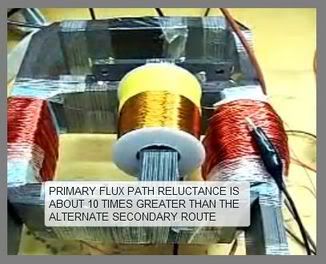
"Primary flux path reluctance is about 10 times greater then the alternate secondary route".
Increasing the secondary windings might cause BEMF to seep back to the primary. Thane reports a COP of 377% with his secondaries under load, measured only in practically useless milliwatts. A pretty flimsey gizmo, not really good for too much currently. Getting more power out is the central problem. I think your new high permeability core variant II with the 1/4" to 2.5" flux path ratio might help solve the problem.
"Thane Heins" Ottawa University BiTT TRANSFORMER DEMO July 11, 2009 - YouTube
I concieved of your latest configuration independently, and wholeheartedly approve! There may be an even simpler approach:
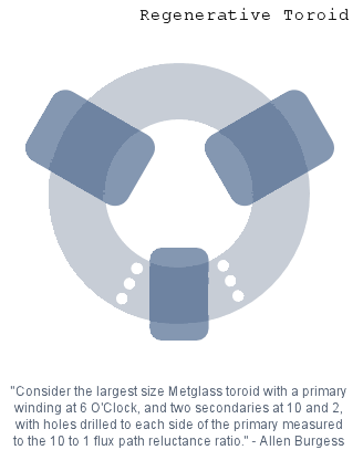
Consider the largest size Metglass toroid with a primary winding at 6 O'Clock, and two secondaries at 10 and 2, with holes drilled to each side of the primary measured to the 10 to 1 flux path reluctance ratio.Last edited by Allen Burgess; 02-25-2012, 07:54 PM.Leave a comment:
-
 Guest repliedEither the material reluctance of the primary core or the size of its
flux path must be 1/10th that of the secondary core?
What if a hi-permeability material is used for both cores, while the
ratio of the flux path is proportioned such that the primary core is
one quarter units in diameter while the secondary core is 2.5 units?
Every bit of the flux generated in the primary core would reach the
secondary coils, and there ought to be an incredible power output...
The system demonstrated to be producing 3.3V on a 27ohm ( 403mW )
load with 104.8V .003A ( 314mW ) into the primary is built such that
it looks like the cores are being underutilized by the frilly amount
of wire on them.
Has this transformer from the [ video ] been upgraded with thicker coils?
Now for another variant - also capable of decoupling from the input?
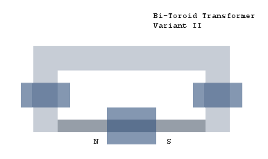
Leave a comment:
-
BITT Core Ratios.
@geotron,
Take a very close look at the picture of Thane's Bi-Toroid varient of 2008 with the linear primary attached to the secondary core. The primary core is the size of a Soda Straw, and the secondary a good sized Angel Cake. I noticed your primary to secondary ratios range from 50% to 20%, which is still twice the proportion you see in Thane's photo. We see thicker primary cores in Thane's other designs, but the reluctance is made up for in weaker material composition. This is the major drawback to Thane's concept, because the gain is restricted to the milliamp range due to the ten times reduced flux reluctance ratio of the primary to secondary core sizes. The primary either winds up too small, or the secondary core too large and unwieldy. I see nothing wrong with your linear BITT design except the primary core is way oversized, assuming the materials share the same degree of reluctance. Your primary core should be spaghetti thin to fit in correct proportion to the secondary in your schematic.
Take another look at the three rings design. Each of the two primary Metglass rings would need very large holes drilled at top and bottem to increase the flux path reluctance by a factor of ten. Anything less then that would allow BEMF to leak back to the primary coil. However, these nano-perm materials have ten thousand times the permeability of the welding wire and oxide castings. The output would increase a thousand fold, but still be in the fractional amp range.
Try clipping half the er7ds mig welding wires to your 3-D Bi-Toroid primary then recheck for milliamp gain in your secondaries!Last edited by Allen Burgess; 03-08-2012, 06:21 PM.Leave a comment:
-
Guest repliedWhat kind of interaction might take place between the primary and
secondary coils with a linear flux path?
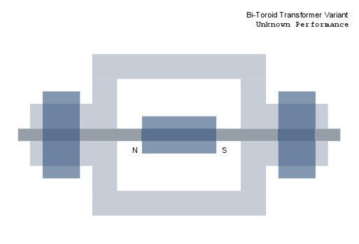
Leave a comment:
-
Guest repliedThe method you've outlined would surely produce a desireable outcome
with the tri-core design. In one of the videos was shown a variant
of the BiTT in which there appears to be a primary core connected
directly with the secondary core in between the two coils as shown

In pursuit of replicating this particular design I have constructed
the following devices, although I am not certain whether this type
of transformer is capable of the same performance as one utilizing
the tri-toroid configuration.
[ video link ]
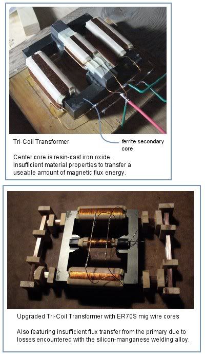
Leave a comment:
-
Triangle R Cores
@geotron,
Let's say we drill four one inch holes through any two R cores in the set of three: Two holes in the top cross bars, and two holes in the bottem cross bars. The corner junction of the two drilled sections would naturally be where the primary coil should be located. These, along with the primary coil, would act the same as the "H" bridge in Thane's Bi Toroid transformer.
The two secondaries would then be linked by the undrilled R core with ten times the flux permittivity through the cross bars, just like the thicker toroid ringing the outside of Thane's "H" bridge. The flux path between the secondarie's undrilled R core would be so much greater then the drilled sections, the BEMF would necessarily travel back and forth between the secondaries only, and not back through the drilled sections to the primary coil. When the BEMF from the seconday in a regular two coil transformer reaches the primary coil, more input power needs to be added.
I don't know how easy it would be to drill holes in the grained silicon steel laminations, but the material is the highest state of the art. I emailed the "BAOTAO" company for a unit price quote in Shanghai China.Last edited by Allen Burgess; 02-24-2012, 04:46 AM.Leave a comment:
-
Guest repliedWould cutting slots in the primary core or otherwise insulating it
from the secondary core legs be enough to generate the effect without
extra flux paths?
With the primary signal fed to the secondary coils through the
same route as the two are connected to harvest the bEMF, will this
hinder the output?Leave a comment:
-
Sawed Bitt.
@broli,
Have a look at the BITT drawing in the attachment. This should help explain why slots would help. Please take note of the cutouts to the middle leg to lower primary permittivity. Drilling four large holes might work even better, or just working them down from the outside with a hand file. I emailed BAOTAO in Shanghai, and plan to ask them if they can build a custom "R core transformer" with reduced permittivity primary rectangle bridges. Baotao's CadCam laser cutting capability should be able to down size the four horizontal primary cross bars by a factor of 1/10th, the ratio Thane Heins has found works best.Last edited by Allen Burgess; 03-08-2012, 06:21 PM.Leave a comment:
-
Why would you saw slots? Besides if you want to leave some space inbetween you could just put 3 R type cores together yourself which is what the 3d core really is.

Softone RW-20 Single-Ended Audio Output TransformerLeave a comment:
-
3D core
All we need to do is saw slots part way through the upper and lower cross bars on either side of the designated primary. Nice find broli!Originally posted by broli View PostLast edited by Allen Burgess; 02-23-2012, 05:15 PM.Leave a comment:
-
By accident I found that there's actually a commercial version of the 3d core, well it's 3 ferrite R cores stuck together. Quite funny coincidence.

R-Core Transformer Manufacturers - R-Core Transformer Exporters and Wholesalers - China SuppliersLeave a comment:
-
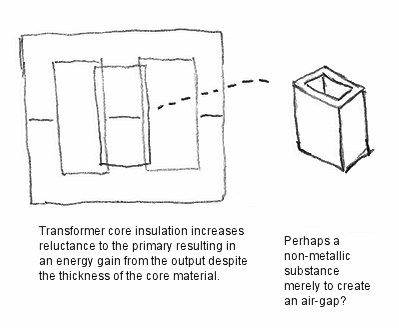
Guest repliedWithout the use of a dual-toroid core for the primary,
instead having the secondary coils on a direct path,
would the following method allow success in decoupling
the output from the source?
Leave a comment:
Leave a comment: