Hi, all
i rigged up a circuit...comprising my function genmerator driving a dual flip flop output to two mosfets ( A & B ), when A is on B is off and vice versa.
connecting from the positive of the cap ( the power source) through the LED...to the mosfet and onto the negative of the cap.
each mosfet has its own LED and uses the same cap as a power supply.
The cap is precharged and then the battery is removed and the circuit is turned on.
using 1.432 Hz and a 50-50 duty cycle... the cap was initially charged up to 4.6V..when the pwm is turned on, the LED's go full bright but within 1/3rd of a second go very dim and the votage on the cap has dropped to about 1.3V.
However... i then re-wired the circuit as it is in the attatchment.
As you can see, each LED & mosfet now uses each half of the captret as its power supply..but only 1 half is ever "Loaded" at any one time ( due to the flip-flopped nature of the circuit )...
again charged to 4.6V...when turned on the LEDS go full bright and it takes about 8 seconds to dim down to the same level of brightness as in the other circuit...meanwhile.the voltage goes down to only 3.6V.and drops only about 0.01V per 1-2 seconds.
Announcement
Collapse
No announcement yet.
Captret - Perpetual Light with Dead Batteries
Collapse
X
-
A captret is an equivalent circuit of a half-wave multiplier.Originally posted by ibpointless2 View PostI don't know what capacitors you guys are opening but my are two strips of aluminum separated by paper soaked in electrolyte. and the whole thing is again wrapped in another piece of paper soaked in electrolyte. So they outer case is aluminum too so it is just acting like another plate.
So i don't know people are so worried about them, the outer case is nothing more than another lead just like the + and -.
So, how can something so simple give a higher voltage then whats in the battery. A flash in a camera has a series of components that do it, the catret is only one thing.
A captret is nothing more than a 3 plate capacitor that does things very different.
An equivalent circuit refers to the simplest form of a circuit that retains all of the electrical characteristics of the original (and more complex) circuit.
GB
Leave a comment:
-
I don't know what capacitors you guys are opening but my are two strips of aluminum separated by paper soaked in electrolyte. and the whole thing is again wrapped in another piece of paper soaked in electrolyte. So they outer case is aluminum too so it is just acting like another plate.
So i don't know people are so worried about them, the outer case is nothing more than another lead just like the + and -.
So, how can something so simple give a higher voltage then whats in the battery. A flash in a camera has a series of components that do it, the catret is only one thing.
A captret is nothing more than a 3 plate capacitor that does things very different.
Leave a comment:
-
A voltage multiplier is an electrical circuit that converts AC electrical power from a lower voltage to a higher DC voltage by means of capacitors and diodes combined into a network.Originally posted by redrichie View Postgravity,
I think he was trying to say if the battery is connected +/- to cap it will only fill up to the voltage on the battery. A camera uses an oscillator to fill up the cap. and your right it is the same thing as a stun gun or taser. But that is not what he is saying.
When the battery is connected +/- to cap then the breakdown voltage of the dielectric isn't exceeded, and the cap will only fill up to the voltage of the battery. When the battery is connected in the captret configuration, then the capacitor's dielectric breakdown voltage is exceeded and conduction occurs just like a diode (this is the virtual or phantom diode Dr. Stiffler has already mentioned). Don't forget the LED is also a diode. This allows the capacitor to be charged slightly higher than the battery voltage. The captret isn't anymore OU than a voltage multiplier by means of capacitors and diodes. Don't kill the messenger.
GBLast edited by gravityblock; 11-20-2010, 06:02 PM.
Leave a comment:
-
gravity,
I think he was trying to say if the battery is connected +/- to cap it will only fill up to the voltage on the battery. A camera uses an oscillator to fill up the cap. and your right it is the same thing as a stun gun or taser. But that is not what he is saying.
Originally posted by gravityblock View PostOh really? A disposable camera flash unit powered by a 1.5 volt AA battery contains a capacitor which may be charged to over 300 volts. Same thing with a stun gun or taser.
GB
Leave a comment:
-
Oh really? A disposable camera flash unit powered by a 1.5 volt AA battery contains a capacitor which may be charged to over 300 volts. Same thing with a stun gun or taser.Originally posted by ibpointless2 View PostUnlike a normal capacitor where it has a limit of how much it can charge up to the captret doesn't. Where a normal capacitor will only fill up to the voltage of the battery a captret will exceed that.
GBLast edited by gravityblock; 11-20-2010, 03:49 PM.
Leave a comment:
-
Originally posted by Jbignes5 View PostThis means that a rather tuned Joule Thief could push the led even brighter. and maybe charge or run a light load as been seen before. I forgot who had the Joule thief hooked up.
By the way if anyone has a good Joule thief circuit they want to try with this just let me know. I'll whip it up fast and see what it can do to my now charging Version 2.0 circuit. I still have yet to put the extra caps on to see if it gets stronger like the old version did.
Leave a comment:
-
A video of captret voltage going over the voltage of battery. aka captret amplifies voltage.
YouTube - Captret amplifies voltage
Normally when you connect a capacitor to a battery it will fill up to the voltage inside the battery, but the captret goes over that voltage. went from 1.302 to 1.550. Where does that extra voltage come from?
Leave a comment:
-
yeah I can drive the led hard with the new setup.
This means that a rather tuned Joule Thief could push the led even brighter. and maybe charge or run a light load as been seen before. I forgot who had the Joule thief hooked up.Originally posted by Joit View PostHi,
the Led should stay in. I have seen slow drops at my Batterie also,
and had to adjust the Pot a bit too.
Therefor i think, anyhow the Pot should do kind of a pulse too
or a dynamic changing of the resistor.
But i figure, when it is such a slow drop as it does,
i can maybe add a solar Cell or a Joule thief.
But ibpointless is right about the higher Potential at the poled Cap,
not sure, if we can replicate it at a unpoled Version.
The other thing really is, it has low amperages at the moment,
i am guessing, that it is a static charge.
But the unpoled Version is may better to produce more Current.
But it is anyway interesting to play with it, it gives me a better picture for
what happens at charging.
By the way if anyone has a good Joule thief circuit they want to try with this just let me know. I'll whip it up fast and see what it can do to my now charging Version 2.0 circuit. I still have yet to put the extra caps on to see if it gets stronger like the old version did.
Leave a comment:
-
Hi,Originally posted by Guruji View PostHi Joit regards about your circuit. I replicated the left one. Does the led should be kept with the circuit to charge the battery or just in the beggining?
Thanks
the Led should stay in. I have seen slow drops at my Batterie also,
and had to adjust the Pot a bit too.
Therefor i think, anyhow the Pot should do kind of a pulse too
or a dynamic changing of the resistor.
But i figure, when it is such a slow drop as it does,
i can maybe add a solar Cell or a Joule thief.
But ibpointless is right about the higher Potential at the poled Cap,
not sure, if we can replicate it at a unpoled Version.
The other thing really is, it has low amperages at the moment,
i am guessing, that it is a static charge.
But the unpoled Version is may better to produce more Current.
But it is anyway interesting to play with it, it gives me a better picture for
what happens at charging.
Leave a comment:
-
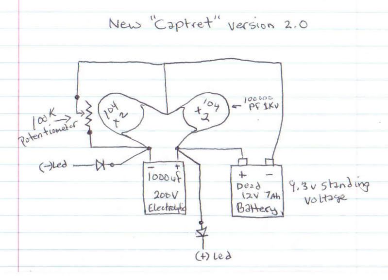
I added more to the circuit.
I put a diode on either side of the led to better protect the light emitting diode from reverse spikes. This reflects them backwards away and I think it is this that is going back to the battery. When I added the diodes they didn't drop the voltage at all. In fact the signal got clearer on the scope now. The led is bright now and the voltage is stable.
I started with 9.30 volts and now it is stable at 9.22 volts with about half to 3/4 brilliance on the led. The led reads 2.62 volts steady and is rated for 3.7 volts. I think I'm gonna add more ceramic caps to the top end in parallel to see if I can get a better swing to the signal. The ceramic caps seem to be very tight seeing they are rated for 1k volts.
I'm running at about .2 uf on the ceramic caps each side (2 in parallel) and they are labeled 104m. The package said they were 100000 pf 1kv.
Oh I forgot this is whith the new stuff I just bought. The Electrolytic cap is a whopping 1000uf 200v and I got a potentiometer with 100k ohm sweep. It is running better then the "captret" single can version and I think it can push more for less now with no degraded performance over time like the single can showed.
I'll let you guys know what the new diagram looks like after I update the drawing so that others can replicate this...
And here is the new diagram:
Last edited by Jbignes5; 11-19-2010, 09:43 PM.
Leave a comment:
-
Circuit
Hi Joit regards about your circuit. I replicated the left one. Does the led should be kept with the circuit to charge the battery or just in the beggining?Originally posted by Joit View PostLeft one is what i did, right one should be yours.
Btw At your Picture what are this waves where your arrow point to before the pot,
another resistor or the waveform?
Right now i can run a LED and keep the Voltage pretty stable with the pot at ~6-7k
Is'nt a LED actually a thin Wire inside what make the Light at a p-n junction?
I did read somewhere something like this.
But oh well, i did not do a long run test for it now.
Thanks
Leave a comment:
-
yeah a video would be good...
Originally posted by ibpointless2 View PostUnlike a normal capacitor where it has a limit of how much it can charge up to the captret doesn't. Where a normal capacitor will only fill up to the voltage of the battery a captret will exceed that.
I hooked up a battery negative to the case of a capacitor, then the positive to the positive of the capacitor. Then i measure positive to the negative of capacitor and the voltage is higher than whats in the battery. How can that be, where is this extra energy coming from? And the voltage just keeps going up, don't know when it will stop but i'll let it run.
I'll post a video of what i mean on youtube in a few minutes.
I think one of the main problems is if you put some real power behind the "Captret" it will fail(destruction of the cap). I am gonna take the advice that Mr. Stiffler relayed. I still believe the problem lies in the design of the cap. The electrolytic was not designed to operate the way we are using it. There are extra forces in the method of the captret that can not be averted. Even if you have a moderate charge on the battery the extra forces that would be generated by the opposing fields in the cap make the cap explode. I know this because I have tested this concept myself.
Taking the design of the flow I recreated the effect in a safe manner. One that we can control. If we release this to the public as is it will be dangerous and I for one, am not willing to let this idea go astray. We need to think about the safety of the device and using the can is not safe. Even if you design a release for the pressure there is no guarantee that the ends do not pop open. Like I said I tested this and with batteries with even a moderate charge on them seem to have enough force to break the cap open. This only does two things. It creates a safety issue and it shortens the life of the cap.
Besides I have designed a way around that by modifying the idea. It's evolving into a more powerful version. Like I said in the original version i saw a wave at the highest settings on my BK Precision scope @ .01 volts per cm. The new setup allows the scope to be set at .02 volts per cm with a two centimeter amplitude. This signal I believe is the reason for the charging on both the cap and the battery.
Leave a comment:
-
I have also noticed this same effect a few days ago. It's a real effect and is easily duplicated.Where a normal capacitor will only fill up to the voltage of the battery a captret will exceed that.
Leave a comment:
-
A very interesting observation - i'll give the same test a go tonight. You explain very clearly what you did and i agree that for the cap to charge higher than the battery seems very strange. hmmmm....Originally posted by ibpointless2 View PostUnlike a normal capacitor where it has a limit of how much it can charge up to the captret doesn't. Where a normal capacitor will only fill up to the voltage of the battery a captret will exceed that.
I hooked up a battery negative to the case of a capacitor, then the positive to the positive of the capacitor. Then i measure positive to the negative of capacitor and the voltage is higher than whats in the battery. How can that be, where is this extra energy coming from? And the voltage just keeps going up, don't know when it will stop but i'll let it run.
I'll post a video of what i mean on youtube in a few minutes.
Cheers everyone for a great thread - have fun and good luck.
Leave a comment:
Leave a comment: