A milliampere-hour (mAh) is a unit of electric charge and is not a unit of energy. One ampere-hour is equal to 3,600 coulombs, the electric charge transferred by a steady current of one ampere for one hour. Milliampere-hour (mAh) is one-thousandth of an ampere-hour (i.e., 3.6 coulombs).
GB
-
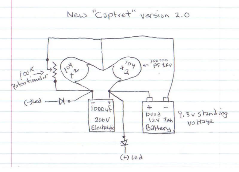
Combine the captret with ibpointless2's self-charging diode load. Maybe by combining the two, the battery won't be needed any longer.Originally posted by Artisan View Post
[Edit:] I hope nobody takes this post seriously, but it won't surprise me if someone does.
GBLast edited by gravityblock; 11-22-2010, 06:21 PM.Leave a comment:
-
ibpointless2 has also made the claim that by connecting one alligator clip to the case of a diode will self-charge a battery in his thread at overunity.com titled, "A diode load self charges battery".
This is almost comical, but at the same time it's sad to see so many people fall for this pointless stuff.
GBLast edited by gravityblock; 11-22-2010, 05:45 PM.Leave a comment:
-
Below is a quote from e2matrix on the captret thread found at overunity.comOriginally posted by Artisan View Post
As you can see, 9 days isn't saying much.Originally posted by e2matrix
GBLeave a comment:
-
 Guest repliedre: Progress
----------------------Originally posted by ibpointless2 View Post
Hello ibp2,
Yes, the blink rate is too fast to notice. Although it all depends on the transistor used, it will blink once the avalanche threshold has been reached. Brightness in my little superbright has not diminished during this time.
The new circuit has both 4700uF caps/captrets connected in parallel (sharing the same o, + and -). I have also placed some inductors in series to the load which seem to greatly increase the discharge/drain time when the battery is disconnected from the circuit. The LEDs stay lit for longer before requiring a 'top-up' from the battery.
Powering LED arrays in this manner has sparked my interest as they are normally wired in series to each other. The larger the array, the larger supply voltage required.
I would be interested any input to making the captret even more efficient!Leave a comment:
-
How fast is your LED blinking?Originally posted by Artisan View Post
Do they blink so fast that they seem to not blink?
If its the same brightness for this long then thats very exciting! Even if it does blink. I made the one you shown me and had it blinking but blink so fast that it was hard to tell if it was blinking, sort of like a strobe light. I might revisit it, I've got a interesting idea that could boost the catret even more.
And the defect to the capacitor was a plain lie. The captret doesn't harm anything, the case is just another lead just like the + and the -.Leave a comment:
-
Guest repliedCaptret with Esaki mod Progress
It's been over 9 days since I have had the captret circuit running with the modified Esaki circuit cited in earlier posts. The PP3 battery is now showing 9.03 volts, and the 3mm superbright LED is the same brightness. All components are still running cool, and I see no defect in my 47uF cap.
Over the weekend I have successfully ran a 28 LED bulb off the same circuit, but from 2 4700 uF caps and an 18V supply (2 PP3 in series). The bulb was shining intensely.
I am currently doing further testing with this.
Thanks again for sharing this discovery ibp2.
Best regardsLeave a comment:
-
Yes...
Trying to get a simulation of the effect the captret is showing. I don't think I got it right yet but it does use the led at higher output without killing the battery. I think I need some diodes in the circuit to direct the flow still. Since there are virtual diode being made between the pos , neg and the casing. The orientation of the diodes is tricky and I haven't had time to concentrate on the design much with the holidays coming up.Originally posted by Guruji View Post
I havent given up on the idea yet but with my circuit at least it does not loose voltage on the battery so far if it is tuned right and it does not use the capacitor in the wrong way either making it safer. There should be a pair of diodes in between the Electrolytic and ceramic caps but getting the right direction of the diodes is frustrating to say the least with me not being able to concentrate on the design. I also believe there is a certain amount of induction from the case to each plate so that is still missing in my design. Once the inductors are included that will give us the amplifying factor we will need to cause a movement in the other side of the circuit. The inductors would be in series with the ceramic caps and then connected to the negative rail.Last edited by Jbignes5; 11-22-2010, 12:43 PM.Leave a comment:
-
@electricity
The captret 1.1 you made doesn't have a complete connection to allow the LED to turn on when in start mode. The negative of the battery never gets hooked up, so the LED never lights. The negative of the battery is only connected when in charge mode. Unless you're using the case to send to negative, but i don't know, am i missing something?
For you design do you always have to get the led to flash first or can you do without?Leave a comment:
-
hi,
power in was measured via ammeter in series from positive of battery & battery voltage...wether using resistors or LEDsLeave a comment:
-
The captret may have a different internal resistance than a capacitor connected in the normal way, and you may need to take this into account. Also, you took power IN measurements with the LED, then took power OUT measurements after replacing the LED with a resistor? Are you sure the math is correct? I'm only suggesting things for you to think about.Originally posted by rave154 View Post
GBLeave a comment:
-
continuing,
i have replaced both LEDs with two 3.3K ceramic coated resistors.
if we use Ohms law to find what the current should be in a standard circuit we get
I = V/R = 4.6 / 3300 = 1.393 mA
running the circuit in normal mode..the current draw appears as 1.41mA...pretty damn close
re-arranging the circuit to be in captret mode ( as described in my earlier post )...current draw appears as 0.37mA
putting the scope across one of the 3.3K resistors(while still in captret mode) gives the image attatched..
settings are, timescale 0.2 mS , 1V per Div
readings are, peak-peak voltage 3.69V, frequency 1.44kHz, RMS voltage 1.38V
doing some quick eye-ball clac's based on the scope shot, it would appear that we have almost 3V continuous across the resistor (minus the lil curved part)..so
I = V/R = 3 / 3300 = 9.09e^-4
P = I * V = 9.09e^-4 * 3 = 0.00272 watts
power IN = 4.6 * 0.37mA = 0.0017 watts
so power IN = 1.7mW and power out = 2.72 mW ???????

ya'll let me know what to make of these findingsAttached FilesLast edited by rave154; 11-20-2010, 09:19 PM.Leave a comment:
-
-
re:- last post,
i now have left the battery connected across the capacitor ( as a top up ).and have an ammeter in series from the +
in captret mode the LEDS are nicely bright, not full but pretty good..and its drawing 3.07mA from the battery (@ 4.6V)
in normal mode, the LEDs are brighter than above, but drawing 107mA @ the same battery voltage
so,
normal = 4.6 x 0.107 = 0.4922 watts
captret = 4.6 x 0.00307 = 0.0141 watts = almost 1/35th of the wattage
however, as stated, the LEDs are a bit brighter in normal mode.
i will re-wire the circuit to use resistors as loads so i can put the scope on them and try and get a more quantitative measurement of the output ( any suggestions for this btw? )Leave a comment:
Leave a comment: