Announcement

Collapse
No announcement yet.

My Motors got me to Tap into Radiant Energy

Collapse
X
 
  • Filter
  • Time
  • Show
Clear All
new posts

  • JohnStone
    replied
    Originally posted by prochiro View Post
    @ JohnStone
    Does your program produce G-Code output for milling? If not could you send me what is does output and I will try to convert it.
    Dana
    Hi Dana,
    Here you are! Production files!
    No idea what it is exactly but I was told there are XGerber and Exellon files herein.
    I was told that this converter can convert those files in G-Code
    Gerber viewer online.

    I hope you can make use of those files.
    JohnS
    Leave a comment:


  • prochiro
    replied
    G-Code

    Hi All & JohnStone
    Does anyone have the milling G-Code for JohnStones Monster V5.1. I use Mach3 program.

    @ JohnStone
    Does your program produce G-Code output for milling? If not could you send me what is does output and I will try to convert it.
    Dana
    Last edited by prochiro; 02-14-2013, 03:18 PM.

    Leave a comment:


  • IndianaBoys
    replied
    Ufopolitics,

    I know you like various information related to Asymmetrical:

    Spinning Disk Trick Solution
    Spinning Disk Trick Solution - YouTube

    IndianaBoys

    Leave a comment:


  • prochiro
    replied
    Hello Nico8K
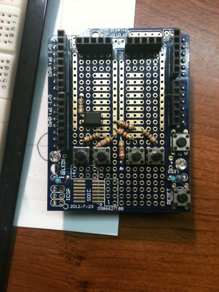
    Thank you for the diagram and code. I thought you may like to see what it looks like on a Leonardo and proto board.

    It works so well and is vary accurate as you said. I even stuck the opto on there for fun. Thanks for the help.
    Dana
    Last edited by prochiro; 02-12-2013, 06:34 AM. Reason: edit.

    Leave a comment:


  • Ufopolitics
    replied
    Great John!

    Originally posted by JohnStone View Post
    Hi Ufo,
    I understand your demands and we will devide them in basic functions and control functions in order to rule them. Divide and impera! (Divide and rule!) That's still true!

    0. Sub basic layer building Arduino pulser and Monster driver. Some means for switching between drive and gen required as well. (Here we struggle just now)

    1. We will decide on what power modes we want to have and what regenerating modes we will have. Those modes can be tested separately.

    2. We will decide on external actions, controls and measurements like thorttle, speed, emergency control or simple mains voltage at output .....

    3.On top of those basic and dumb functions we set a control layer. This layer is the "intelligence" we need to ponder on, program it and test it. Fortunately this layer can be tested thoroughly without any external reality - thus no accidents.

    4. On top of those 3 layers we get a layer for monitoring and surveillance. Independently of layers above it makes use of same input and output signals but checks plausibility. Any abnormal condition (like too much rpm) will shut down the system in smart and safe way. Thus program errors can be dealt with in a safe way.

    Those layers do not need to be performed by a single micro only - too dangerous and too difficult to debug.
    ----------------------------

    Regarding the first two layers:
    What controls the speed of the motor? You mentioned to control them by pulse speed similar to a stepper motor. Is that for low rpm only or will it contuinue at higher rpm? Do we drive it in a kind of synchronous mode?
    Sorry for this question - I did not get it in my mind yet.

    rgds
    JohnS
    Hello John,

    That's great! I am glad you've got the path...and understanding.

    Now, I do not want you to get confused with stepper motors and our Asymmetric In/Out Coils...they are different.

    Stepper Motors like the name spells are based on "Step Coils", coils ahead of others, wrapped around a steel frame lamination or a permanent magnet "special layered" core... we could easily roll them over a linear pattern...and will become a "linear stepper motor"...

    Our Asymmetric Coils are different...they develop a much more Dynamic Pattern...a Spiral...and that can not be rolled over and become linear...just because its Asymmetrical Shape and Magnetic Patterns.

    If once I spoke about steppers was just to bring in the way they get their pulses in different Phases...however, that also happens (as I have also mentioned) in Brush-Less Designs.


    Hope You understood my explanation...


    Kind Regards


    Ufopolitics

    Leave a comment:


  • Ufopolitics
    replied
    Great Nico!

    Originally posted by nico8k View Post
    Hello Ufo, John, Cornboy and All

    I am totally agree on using same platform, it is easier for testing and debugging if we all walk in the same path.
    I've recommended to Cornboy the Arduino Mega assuming the idea on using only one arduino, but as John said... it is better to use another Arduinos for different tasks... "think in modules" you are right John!

    In learning programming you always start with the great "Hello World" so lets start with a simple project and see how it goes...
    In case you have not seen my post sharing my PWM project:

    Dropbox PWM Project

    [ATTACH]12939[/ATTACH]

    Anyone who has an Arduino please download the files and make some test.
    When we ALL have this simple PWM project running we can start to upgrade it or even make new ones on request.

    @John this project is just a simple PWM to feed your FET driver, please check what needs to connect to your driver. Thanks.

    Regards

    Nico

    Hello my friend!

    Wow!, impressive!, that is great and looking beautiful!!

    We are gonna be "Rock and Rolling" very soon!!

    Un Abrazo Hermano!


    Ufopolitics

    Leave a comment:


  • Ufopolitics
    replied
    Thanks to You QV

    Originally posted by qvision View Post
    Thanks for taking the time to explain.

    I will shut up and build it ;+}


    All the best,
    Hello Qvision,

    Thanks for that answer, like John Stone wrote...not many people will take it/react like You did.
    This answer makes you very big and very smart to me, and I will help you as much as I could, so you make a HECK of a BUILD!!

    The Three Pole will teach you many other interesting things...

    Warm regards, and my apologies if i was a bit too rough/tough on you...however, my intentions worked out...I wanted you to focus more on build than tinkering...and your electronics skills are great...so you will become a great builder of this Machines and their controls.

    Ufopolitics

    Leave a comment:


  • nico8k
    replied
    Hello Ufo, John, Cornboy and All

    I am totally agree on using same platform, it is easier for testing and debugging if we all walk in the same path.
    I've recommended to Cornboy the Arduino Mega assuming the idea on using only one arduino, but as John said... it is better to use another Arduinos for different tasks... "think in modules" you are right John!

    In learning programming you always start with the great "Hello World" so lets start with a simple project and see how it goes...
    In case you have not seen my post sharing my PWM project:

    Dropbox PWM Project

    Click image for larger version

Name:	NicoPWMSwitch Board.jpg
Views:	1
Size:	733.8 KB
ID:	454585

    Anyone who has an Arduino please download the files and make some test.
    When we ALL have this simple PWM project running we can start to upgrade it or even make new ones on request.

    @John this project is just a simple PWM to feed your FET driver, please check what needs to connect to your driver. Thanks.

    Regards

    Nico
    Last edited by nico8k; 02-12-2013, 01:29 AM.

    Leave a comment:


  • JohnStone
    replied
    Originally posted by qvision View Post
    Thanks for taking the time to explain.

    I will shut up and build it ;+}

    All the best,
    Hi qvision,
    sorry for chiming in in your discussion with UFO!
    I want to say: you showed up big grandeur. Few react in this way. You will not regeret your step!
    JohnS
    Last edited by JohnStone; 02-12-2013, 11:16 AM.

    Leave a comment:


  • qvision
    replied
    OK thank you.

    Originally posted by Ufopolitics View Post
    Hello Qvision,


    That is a good Choice, simpler Machine, yet, very powerful...


    In My Opinion (IMO):

    IF, Before you even start taking apart your original motor...you start "assuming/theorizing/believing" that a Motor that I have displayed here a while back, that I have displayed so many angle interactions and explanations... and that has been replicated by so many people here...AND that BEFORE THAT...I have wounded hundreds of this Motors, in all sizes and "colors"...thinking something is wrong with it?...To me that is a "daring attitude" without the right knowledge...but to You... it would be an obstacle to "see" your Future Asymmetric Motor running properly...other words, and also simpler..."You will be programming yourself for failure..."...Ok?


    WRONG ASSUMPTION WITHOUT EVEN A REAL TEST.Ignorance is DARING...

    An old phrase that I love...AND VERY TRUE


    Regards


    Ufopolitics

    PD: And Please, a Message to All:

    ALL Motors and Interaction Related Posts, let's keep them together in the other Asymmetric Machines Thread.

    It will be of much more easier access for new coming members or anyone to have all related Material in just one Thread...and not be scattered all over...
    Thanks for taking the time to explain.

    I will shut up and build it ;+}


    All the best,

    Leave a comment:


  • Cornboy 555
    replied
    What a Community spirit!

    Thanks, for everyones input on this control system, i totally agree that the system we use should be as universal to all members as possible, and the ability to exchange codes etc would be of real importance for someone like myself.

    When it came to programing or troubleshooting i would be in the dark till i learn this tech.

    I am completly in your hands Guy's, i will use what ever you recomend.

    Thanks once again everyone,

    Regards Cornboy.

    Leave a comment:


  • JohnStone
    replied
    Hi Ufo,
    I understand your demands and we will devide them in basic functions and control functions in order to rule them. Divide and impera! (Divide and rule!) That's still true!

    0. Sub basic layer building Arduino pulser and Monster driver. Some means for switching between drive and gen required as well. (Here we struggle just now)

    1. We will decide on what power modes we want to have and what regenerating modes we will have. Those modes can be tested separately.

    2. We will decide on external actions, controls and measurements like thorttle, speed, emergency control or simple mains voltage at output .....

    3.On top of those basic and dumb functions we set a control layer. This layer is the "intelligence" we need to ponder on, program it and test it. Fortunately this layer can be tested thoroughly without any external reality - thus no accidents.

    4. On top of those 3 layers we get a layer for monitoring and surveillance. Independently of layers above it makes use of same input and output signals but checks plausibility. Any abnormal condition (like too much rpm) will shut down the system in smart and safe way. Thus program errors can be dealt with in a safe way.

    Those layers do not need to be performed by a single micro only - too dangerous and too difficult to debug.
    ----------------------------

    Regarding the first two layers:
    What controls the speed of the motor? You mentioned to control them by pulse speed similar to a stepper motor. Is that for low rpm only or will it contuinue at higher rpm? Do we drive it in a kind of synchronous mode?
    Sorry for this question - I did not get it in my mind yet.

    rgds
    JohnS

    Leave a comment:


  • Ufopolitics
    replied
    Hello Qvision,

    Originally posted by qvision View Post
    Hi all
    Hello Qvision,

    i've decided to try with a 3-pole motor due to it's simplicity and just to observe the difference in behaviour between that and a standard motor :

    That is a good Choice, simpler Machine, yet, very powerful...

    One thing is confusing me and i would like to clear it up before i start work on this.

    In the description above it says the advantage of this winding is that there are two coils outputting and only one coil inputing.

    I've analysed the firing sequence of the coils and this seems to be wrong.
    In My Opinion (IMO):

    IF, Before you even start taking apart your original motor...you start "assuming/theorizing/believing" that a Motor that I have displayed here a while back, that I have displayed so many angle interactions and explanations... and that has been replicated by so many people here...AND that BEFORE THAT...I have wounded hundreds of this Motors, in all sizes and "colors"...thinking something is wrong with it?...To me that is a "daring attitude" without the right knowledge...but to You... it would be an obstacle to "see" your Future Asymmetric Motor running properly...other words, and also simpler..."You will be programming yourself for failure..."...Ok?

    Using the coil colours in the diagram (Gree, Blue and Turqoise) the input firing sequence is :

    Green.
    Green and Turq.
    Turq.
    Blue and Turq.
    Blue.
    Green and blue.

    In the list of input charges above, the coils not on each line are obviously outputting.

    When you analyse the sequence you can see that the input and output charges balance out, they sum to zero.

    WRONG ASSUMPTION WITHOUT EVEN A REAL TEST.
    What are people's thoughts on this ?


    Thank you,

    QV.
    IMO?...What Do I think of this?

    I will tell you...

    Ignorance is DARING...

    An old phrase that I love...AND VERY TRUE


    Regards


    Ufopolitics

    PD: And Please, a Message to All:

    ALL Motors and Interaction Related Posts, let's keep them together in the other Asymmetric Machines Thread.

    It will be of much more easier access for new coming members or anyone to have all related Material in just one Thread...and not be scattered all over...
    Last edited by Ufopolitics; 02-11-2013, 07:59 PM.

    Leave a comment:


  • Ufopolitics
    replied
    May add My Opinion...

    Originally posted by JohnStone View Post
    Hi Nico,
    I agree with you totally - from technical view. But it might be essential that all of us use the very same processor platform (i.e. 328). There is no other way in order to provide newbies like Cornboy and many others unnamed with programs being fully shareable.
    Newer platforms differ in USB to be native in order to enable USB native protocols in order to simulate keyboard, mouse to a PC. But this is of no concern for us.


    Another concern is the basic form factor:

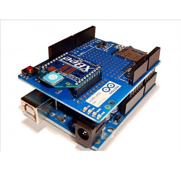
    1. Native form factor requries a "shield" fitting to the connectors of arduino istself.
    Native Arduino form factor:


    Arduino shield for additional electronics:


    Ardunio stacked with sield:


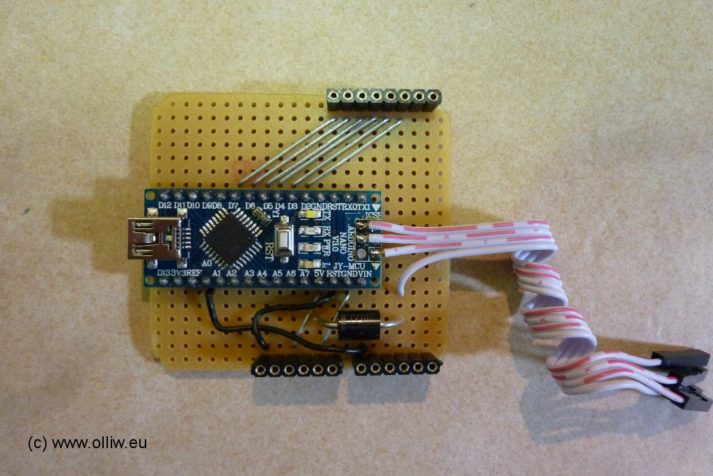
    2. Slim line: nano, Tosduino ... can be mounted an a normal IC socket at our breadboards.
    Prepared for DIL socket:


    Example:

    Usage:


    It can be made ready for screw terminals s well:


    Now my question is: what formfactor and processor type will help our community most in order to get various electronic tastks done easy? We are loaded with the task to recommend a unified solution because most contributors can not decide themselves. And they are not able to modify given solutions to their specila setup.

    You Nico and I are fans of the small form factor #2 becaue of very easy adaption ot bread boards. Others might go another way.

    We shall decide at least for ame procesor pltaform. Different formfactors might be dandable.

    Nico, please understand, I do not want to argue but get for our untrained members most of eficiency.

    JohnS

    Hello John Stone, Hello Niko, Hello Cornboy, Hello to All,

    Now, John, as you wrote , and I am in total agreement with your opinion above.

    I believe We should keep within one Microprocessor Module, as long as it will work with most of our builds. However, knowing some PC Codes Software...as also some programming...I suggest we stay within one design, as long as that one fits say a V4 for Imperial as a V6 for Cornboy...it would be much simpler for transferring codes between Us, edit-resend info of right running software codes, etc,etc...other words, we will be tuned within same "Language" and Hardware.

    From the Technical point of view...it would be best a small microprocessor that we could take off our controller box, let's say from our future electric car, or simply from our backyard Generator...or just plug our Laptops to a USB Connector on control console...and be able to program or analyze-trouble shoot any errors/failure, etc...

    All Electric/Electronic Motor Controllers Oscillators have a dedicated separate board for low voltage signals...as from there it connects to the Accelerator Potentiometer...so, it would be great we program our processor-low voltage board and with a couple of screws off we insert it back to the whole unit.

    Now, I am not familiar with Arduino Interface...but I will, eventually, which is not going to be much big of a deal...but again to Niko and John Stone:

    We could easily enter into the API of Arduino and be able to modify main programming from its Native Embedded Language right?
    Or for newbies into programming...say we prep the whole code...and text it...done deal...just save and run codes...install and press accelerator...we are driving down the road...

    As I am pretty sure, Arduino have already a pretty good Interface to operate this pulsing here of four to six square waves with a dead time in between...right?

    Now related to what we need from Arduino...besides a V4-V6 Square Pulses with space between...Plus the other platform to attach to it, in order to "execute" those codes...


    All of you are by now pretty Familiar with Asymmetric Tech Machines...and am referring to Basic Operation...Then You all know we do not need to operate this Machines at Full Blast RPM's at all times...and that's no problema, cause we just decelerate that Pot...but that's not all...We need, that whenever we decelerate those "Idling Coils" will become a "Re Generative" System that would Retro-Feed or Feed Back their Generated Energy back to Storage Capacity Banks...whether Caps, Ultra-Caps or Batteries Bank (More suitable here would be a nice Maxwell Ultra-cap Bank...and a very nice BMS (Battery Management System) but...that is beyond our reach by now...so, say a Regular Cap-Bank with a Charger to Lead-Acid Batteries...

    So getting back to Electronics and Arduino...we need to "Teach" that Microprocessor...that whenever a Signal Out becomes Flat (No Signal, Zero, turned off) Arduino then will channel through ANOTHER FET Module...the Incoming Energy flow to route it properly...Now my question John, and that would save time IF it is Electronically possible to do from our FET Gate Monster Module?...meaning, that when "No Signal" going Gates...then that means immediate reverse flow...and would be directed properly.

    I will explain in Imperial as the simpler one...then MAG 3 from Cornboy...

    Say in Imperial we need "sometimes" a Full V4 Signaling those FET's (Full Blast-Turbo-Boost)...but, sometimes we do not, meaning we could easily drive with just a V2 or EVEN a V3 (idling, no load to drive Generator Head, etc,etc...then, those one or two Channels Off...will become automatically and Instantly Generating Gates...

    In MAG 3 is a bit more complicated because Cornboy Build have Wound Stators, that will also be pulsing in Sync with Brush Gates...as also, since it has more I/O Gates (six at Brushes) PLUS another Six for Stators Primary-Secondaries...that in their time Off...will be allowing "Our Purple Lady to come in...So, yes, this MAG 3 has, definitively, much more options...

    And this is not just a matter of commanding <Turning Off Gate/Go to BMS>...But also be able to Rotate/Alternate those Gates between them...to cool off, to change flow and to "clean" Machine Coils from parasitic, random spikes/flows.


    Sorry if too long of a post...but I believe we need to know where we are before proceeding to Make, Program or buy the Arduino...


    Kind Regards to All


    Ufopolitics

    We need to clear/sort that part out before we decide a complete build of the Electronic Drivers.
    Last edited by Ufopolitics; 02-11-2013, 06:18 PM.

    Leave a comment:


  • qvision
    replied
    3-pole motor rewind ...

    Hi all

    i've decided to try with a 3-pole motor due to it's simplicity and just to observe the difference in behaviour between that and a standard motor :


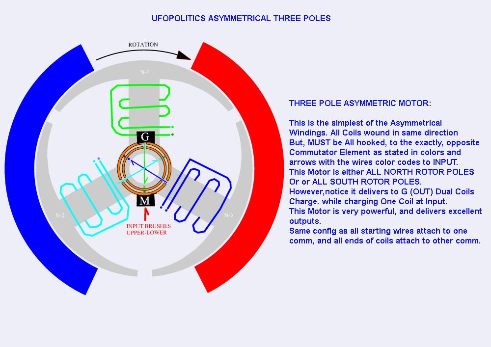
    One thing is confusing me and i would like to clear it up before i start work on this.

    In the description above it says the advantage of this winding is that there are two coils outputting and only one coil inputing.

    I've analysed the firing sequence of the coils and this seems to be wrong.

    Using the coil colours in the diagram (Gree, Blue and Turqoise) the input firing sequence is :

    Green.
    Green and Turq.
    Turq.
    Blue and Turq.
    Blue.
    Green and blue.

    In the list of input charges above, the coils not on each line are obviously outputting.

    When you analyse the sequence you can see that the input and output charges balance out, they sum to zero.

    What are people's thoughts on this ?


    Thank you,

    QV.

    Leave a comment:

Working...
X