Announcement

Collapse
No announcement yet.

My Motors got me to Tap into Radiant Energy

Collapse
X
 
  • Filter
  • Time
  • Show
Clear All
new posts

  • Lightworker1
    replied
    Originally posted by JohnStone View Post
    Discussion related to recent post #4190 of lightworker.
    @Lightworker: Thanks for your activity and recent post!
    @ALL: who want to proceed with further measurements via Arduino! Please be aware to design yoyur setups to be shareable to othrs.
    AND
    Please be prepared that our setups will emit severe electromagnic disturbance on environment being seated or connected near by. And we want our Ardunio(s) to collect measurements and not wired estimations on current, voltage.....
    Apart these facts we want to protect our PCs as well from damage.
    We need to see facts in bigger context:
    The main concern ist hat most measurements need to relate to a reference point (GND usually). It will be no problem if measuring a single value only. Implications begin with having different reference points like voltage and current. i.e. current measurement will shift voltage figures - especially if we suffer on high current spikes. Thus we need to search for well separated sensors.

    Hall sensor:
    Yes this is the way to go for rpm. We may extend it for position sensor later on.

    Current measurement:
    It is very difficult to add a shunt for current measurement in GND line at high currents. It shifts GND point and at higher current and the value of the shunt is muinute.
    It is very difficut as well to measure current in plus lline as the voltage is jumping excessively. Industry offers lots of very expensive current transducers but recent technology makes cheap solutions available.
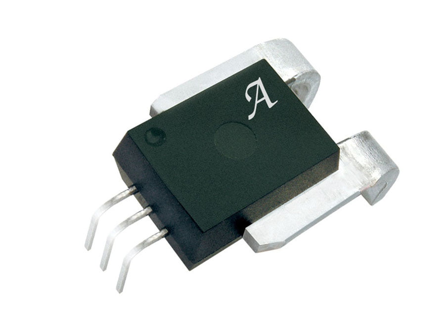
    i.e.: ACS758 from Allegro. Available in different amp ratings, through hole and simple to use. (I confirm this suggestion uttered by another contributor some time ago!)

    Needs possibly a simple opamp for preamplification.

    Serial link:
    Ardunios commnicate via USB - unfortunately GND connected to PC. Of course we can run them from battery without PC but then we have no chance to gather data by PC.
    I found some very cheap BlueTooth addons at eBay for Arduino.

    Thus we can instantiate a virtual BT com port to PC. Thus we can add several dedicated Arduino setups wherever we want (10 kilovolt if we decide to! )
    USB port still required for program download.

    I inted to explain that there are some facts to be considerd in order to get easy to use modules ready to use for all members.
    JS


    Hello JohnStone - Many thanks.

    In any R&D as you know challenges will always sprout like mushrooms.
    Well we are here with desire to solve them.

    As per your suggestion, Allegro Current Sensors are great, with feature like:

    The thickness of the copper conductor allows survival of the device at high overcurrent conditions.
    The terminals of the conductive path are electrically isolated from the signal leads (pins 1 through 3).
    This allows the ACS758 family of sensor ICs to be used in applications requiring electrical isolation
    without the use of opto-isolators or other costly isolation techniques.


    and great features.

    There is nothing more rewarding and satisfying than sharing and moving forward with the progress. I hope our goal is much closer now.

    in the last few days, I have decided to use multiple arduinos connected by I2C bus. The more I looked at I2C bus the more I liked it

    For now I have my main Arduino as Leonardo with I2C LCD screen 20 charaters by 4 Lines on order.

    That way one also saves on lot of Arduino pins.

    For remainder I going to spread out the processing over to the single function cheap arduinos all connected by the I2C Bus.

    The I2C bus just consists of two wires, for example, on arduino UNO, pins A4 for SDA (data) and A5 for SCL (clock) and ofcourse we must also use +5V and common GND.

    On I2C bus each device has its own address. There are many applications, such a real-time clocks, digital potentiometers, temperature sensors, digital compasses, memory chips, FM radio circuits, I/O expanders, LCD controllers, amplifiers, and so on already I2C compatiable.

    You can have more than one device on the bus at any time, in fact the maximum number of I2C devices used at any one time is 112.
    Each device has its unique I2C Address.
    Well that should full fill all our needs at this time.

    For now I will be using cheaper version of Arduino as SLAVES, based on the AtMega328 DIL and Arduino as Leonardo as MASTER

    All the components for ATMega328P are about $12.

    Introductory YT uses prior model chips but the idea is clearly presented

    Introduction to the Arduino Microcontroller - YouTube


    Various AVR Chips compared here.
    ATmega8, ATmega48, ATmega88, ATmega168, ATmega328 Comparison

    ATmega8 ATmega48 ATmega88 ATmega168 ATmega328


    I am also now starting on the first set of tests results with whatever I have at hand.


    Wish warmest regards for all.

    light

    Leave a comment:


  • JohnStone
    replied
    Originally posted by Midaztouch View Post
    John,

    Thank you for welcoming me a couple of weeks ago. You had asked me if I had read this thread. At that time, I would have had to say NO but as of today, I can say YES! It was really interesting reading real-time research and development in an open forum like this. It feels like being part of a research team and sharing each other's notes. I have to admit, I didn't know what a Fet, mosfet, gate, drain, 555, monster driver, ect... were at the start. I had to use Wikipedia, YouTube, eBay, companies homepages, ect.... I did a lot of extra reading to learn with those parts were. Within two weeks, I have gained some basic knowledge on how to build a driver.

    I think that the coordinated effort from people all over the world to focus on this one project simultaneously is truely inspirational! Coming from an idea/concept and then actually bring it into reality through the R&D section. Also keeping it basic as UFO instructed, so that newbies, like myself, could understand. You've made great strides in less than a year! I am impressed with everyone who has contributed to this thread. It started of slow but your are full steam ahead and still gaining speed quickly! You guys have been the Wikipedia's definition of TEAMWORK!

    Keep it Green and Clean

    Richie
    Richie,
    you are welcome in open R&D team! :-)
    You can understand a FET like a relay being controlled by a voltage only. Show up voltage at gate and it will contact D/S freely without drawing any additional power.
    Take voltage away and it will close its contacts.
    Unfortnately the voltage control leg (gate) is harnessed with drain and source pins of FET (contacts if you envision a relay) via internal inherent capacitors. They disturbe like pest. Most of implications and disussions relate to ovecoming and tame those drawbacks.
    I can encourage you to take a PSU, bulb and FET and test it by connecting gate to 12V / let gate open / connect it to GND / let it open ......
    FETs are forgiving a lot except overvoltage and excessive heat. Please understadn monster driver to be a reference for high power. For lower power exercises you can keep it much more simple in order to learn basic behaviour.
    rgds
    JohnS

    Leave a comment:


  • Midaztouch
    replied
    Finished reading this thread. UFO, John and all, I applaud you all!

    John,

    Thank you for welcoming me a couple of weeks ago. You had asked me if I had read this thread. At that time, I would have had to say NO but as of today, I can say YES! It was really interesting reading real-time research and development in an open forum like this. It feels like being part of a research team and sharing each other's notes. I have to admit, I didn't know what a Fet, mosfet, gate, drain, 555, monster driver, ect... were at the start. I had to use Wikipedia, YouTube, eBay, companies homepages, ect.... I did a lot of extra reading to learn with those parts were. Within two weeks, I have gained some basic knowledge on how to build a driver.

    I think that the coordinated effort from people all over the world to focus on this one project simultaneously is truely inspirational! Coming from an idea/concept and then actually bring it into reality through the R&D section. Also keeping it basic as UFO instructed, so that newbies, like myself, could understand. You've made great strides in less than a year! I am impressed with everyone who has contributed to this thread. It started of slow but your are full steam ahead and still gaining speed quickly! You guys have been the Wikipedia's definition of TEAMWORK!

    Keep it Green and Clean

    Richie

    Leave a comment:


  • JohnStone
    replied
    Originally posted by boguslaw View Post
    ....
    btw : is it possible to send signal to two mosfet drivers (same chip TC4420) in the same moment (mosfet drivers in parallel) and this way driving a bank of 10 mosfets better with single PULSE from two drivers ? One single chip has 6A pulse current while two of them could have 12A but is that possible at all ? Simply,I have troubles finding 12A mosfet driver in my country.
    Hi Bouslaw,
    Monster driver was designed to switch 100A as fast and cool as possible - a reference. There are plenty of otehr ways availyble. Internet is full of them.
    We need to drive FETs up to 12V in order to open them fully (Arduuino is not ablet to drive 12V!). One simple circuit is that from Lester 555 + NPN/PNP pair.
    Such a circuit can drive ANY number of FETs - but slow only.
    In fact there is no good or bad - it depends on the requiremetns of the setup.
    JS

    Leave a comment:


  • boguslaw
    replied
    Originally posted by kEhYo77 View Post
    @bogusław

    Siema.

    It is certainly possible to send out a signal at the same time via up to 8 pins with one Arduino instruction using registers directly (setting bits on PORTB and PORTD).
    Now, for this to work all connections to driver chips must be of the same length.
    Siema. Thank you. Interesting point of view. I doubt fets could be fully opened without using a driver to fill gate capacitance fast enough, that's my problem so far, I don't want to spoil my FET bank and have to carefull prepare all tests. Your solution is good if we could use identical mosfet drivers for each one and open them in the same moment....but that would be very costly

    Leave a comment:


  • kEhYo77
    replied
    @bogusław

    Siema.

    It is certainly possible to send out a signal at the same time via up to 8 pins with one Arduino instruction using registers directly (setting bits on PORTB and PORTD).
    Now, for this to work all connections to driver chips must be of the same length.

    Leave a comment:


  • boguslaw
    replied
    A little help could be maybe using very cheap nRF24L04 tranceivers (2$ for one on ebay with free shipping from Honk Kong) connected to Arduino . Max speed is 2Mhz.They are working in pairs (you need to buy two to be workable ). I have been succesfully using them to pass data collected from my coal burner up to 15 meter to my bedroom (I watch temperature of stove and in garage) (it's however an edge of range however through thick walls) it was my first project with Arduino

    Options are endless ; you can manage circuit like a robot by sending commands or just collecting data from circult wirelessly.

    I could help as much as I learned Arduino so far (during last few weeks)

    JohnStone

    btw : is it possible to send signal to two mosfet drivers (same chip TC4420) in the same moment (mosfet drivers in parallel) and this way driving a bank of 10 mosfets better with single PULSE from two drivers ? One single chip has 6A pulse current while two of them could have 12A but is that possible at all ? Simply,I have troubles finding 12A mosfet driver in my country.

    Leave a comment:


  • Donald Haas
    replied
    [QUOTE=prochiro;227194]@ Donald and All

    Hello bro, glad to see you are learning and testing. I would strongly suggest that as John mentioned, create the Monster as complete up to the fets. That part is stable to drive anything. Then create a board for each pair of fets as John showed in example. This way each time a fet goes, you will not loose the whole thing. As time goes on, the fet stage may change some, so it will be easy to update. That fet stage must have the protection diodes attached or pooooof. John is correct about not needing a strong pulse level from the generator.

    Hi Dana and All,

    I've spent a lot of time in the Target software and have enjoyed learning how to solve layout problems. I decided to redo the sections A - E in John's monster because I failed to get through my first build attempt.
    I layed it out where it's was easy for me to etch and build. It is not so densely populated. I only have one trace going between the opto pins, for example instead of 3. No jumper and even bigger traces where large is called for. I kept looking at the F section and decided to change it so the busses are closer to the fets and with no increased signal travel.
    I've etched Section F on a separate board which butts up against the MIC output with no increase in distance between mic and fets.

    I just gave it all the smoke test and it works.


    I CERTAINLY DO NOT CLAIM THAT ANYTHING I HAVE DONE IS AN ELECTRICAL IMPROVEMENT.


    I've just enjoyed the process.

    The fets are connected to the D and S busses like John shows (triangles) except the wires are a little shorter.

    If I can get excellent results I'll show what I have. Otherwise it is just a learning experience.

    I've put a 6 position rotary switch on my pulse gen and I'll see if I can work out a complete selection between 100hz and 5khz for example.

    The square waves are very nice so far.

    Keepin' on,

    bro d

    Leave a comment:


  • JohnStone
    replied
    Originally posted by IndianaBoys View Post
    JohnStone,

    From "Cure For All Diseases":
    ....
    Be well my friend!

    IndianaBoys
    Thanks!
    Know it and have reingeneered quite expensive devices. They all are based on basic plans even if they come with external gold and silver plating! Never saw such expensive 555 devices!
    Thanks:
    JohnS

    Leave a comment:


  • JohnStone
    replied
    Discussion related to recent post #4190 of lightworker.
    @Lightworker: Thanks for your activity and recent post!
    @ALL: who want to proceed with further measurements via Arduino! Please be aware to design yoyur setups to be shareable to othrs.
    AND
    Please be prepared that our setups will emit severe electromagnic disturbance on environment being seated or connected near by. And we want our Ardunio(s) to collect measurements and not wired estimations on current, voltage.....
    Apart these facts we want to protect our PCs as well from damage.
    We need to see facts in bigger context:
    The main concern ist hat most measurements need to relate to a reference point (GND usually). It will be no problem if measuring a single value only. Implications begin with having different reference points like voltage and current. i.e. current measurement will shift voltage figures - especially if we suffer on high current spikes. Thus we need to search for well separated sensors.

    Hall sensor:
    Yes this is the way to go for rpm. We may extend it for position sensor later on.

    Current measurement:
    It is very difficult to add a shunt for current measurement in GND line at high currents. It shifts GND point and at higher current and the value of the shunt is muinute.
    It is very difficut as well to measure current in plus lline as the voltage is jumping excessively. Industry offers lots of very expensive current transducers but recent technology makes cheap solutions available.
    i.e.: ACS758 from Allegro. Available in different amp ratings, through hole and simple to use. (I confirm this suggestion uttered by another contributor some time ago!)

    Needs possibly a simple opamp for preamplification.

    Serial link:
    Ardunios commnicate via USB - unfortunately GND connected to PC. Of course we can run them from battery without PC but then we have no chance to gather data by PC.
    I found some very cheap BlueTooth addons at eBay for Arduino.

    Thus we can instantiate a virtual BT com port to PC. Thus we can add several dedicated Arduino setups wherever we want (10 kilovolt if we decide to! )
    USB port still required for program download.

    I inted to explain that there are some facts to be considerd in order to get easy to use modules ready to use for all members.
    JS

    Leave a comment:


  • IndianaBoys
    replied
    Originally posted by JohnStone View Post
    Unfortunately they were not interesed at all.
    Gut severe flu - makes me silent :-(
    rgds John
    Free Zapper Plans | Build Your Own Zapper

    Schematic:


    Bill of Materials:
    Parts List to Build Your Own Zapper

    Be well my friend!

    IndianaBoys
    Last edited by IndianaBoys; 03-17-2013, 12:57 PM.

    Leave a comment:


  • JohnStone
    replied
    Originally posted by Cornboy 555 View Post
    Hello John Stone, and all, did you have a response from RM Cybernetics on making Monster Drivers?

    Hope all is well,

    Regards Cornboy.
    Unfortunately they were not interesed at all.
    Got severe flu - makes me silent :-(
    rgds John
    Last edited by JohnStone; 03-17-2013, 07:37 PM.

    Leave a comment:


  • Cornboy 555
    replied
    Response?

    Originally posted by JohnStone View Post
    Thanks for hint. I dropped a message to them. I offered the pulser as open source for them and asked for a quote for 20 kits.
    JohnS


    Hello John Stone, and all, did you have a response from RM Cybernetics on making Monster Drivers?

    Hope all is well,

    Regards Cornboy.

    Leave a comment:


  • JohnStone
    replied
    Switching clusters of FETs:
    One serious implication at FETs is they contain an internal capacitor of about 1nF at gate leg. Adding other capacitive effects we have to account up to 8...10nF at each FET for driving.
    As everybody knows a capacitor is being charged by current. If we require fast switching we need to provide more amps within the given time slot.
    Calculated at quite ideal conditions under load and 12V drive voltage and 12A drive current:
    2 FETs (20nF): 50ns for charge voltage of 11V
    4 FETs (40nF): 100ns for charge voltage of 11V
    8 FETs (80nF): 200ns for charge voltage of 11V

    Please note:
    • The figures above relate to charging of the gate capacitance. We need ot account for oether effects - so take the time above twice.
    • Discahrge will take more time.
    • Switching time enteres linearly into heat generation
    • More FETs will spread to a longer area on heat sink -> longer leads -> slower switching and possibly spurious oscillations.
    • connect leads to gate symmetrically (same length) and provide a GND lead back to GND of driver of same length
    • Use bus bars of heavy copper for connecting FETs


    Please understand there are not general instrucables to crowd FETs. You need to know your setup and be able to check for proper function.
    JS


    .

    Leave a comment:


  • boguslaw
    replied
    I strongly feel that to get any visible effect we must go below 0.020 ohm like Ismael Aviso was teaching us. (I'm working on something else (solid state device) but the idea is the same). It means as John described , a lot of amperes.
    is your driver able to switch bank of mosfets so fast that every one is opened in the same moment ? so far I plan to use Arduino with optocoupler with mosfet driver and 10 fets. what do you think about that idea ? maybe you can use it too look again at Aviso videos at his bank of IRF840 fets

    Leave a comment:

Working...
X