Announcement

Collapse
No announcement yet.

Bi-toroid Transformer of Thane C. Heins

Collapse
X
 
  • Filter
  • Time
  • Show
Clear All
new posts

  • Bob Smith
    replied
    My pleasure Mike.
    Nice pics. Your enthusiasm is contagious.
    Have a good day.
    Bob

    Leave a comment:


  • BroMikey
    replied
    Highlights

    Here are a few I liked


    Thanks Bob


    Mike

    Leave a comment:


  • BroMikey
    replied
    Wow Great Munchies

    Originally posted by Bob Smith View Post
    Mike
    Have you seen all these slideshare presentations (you can select them from right column)
    Pdi Ceo Thane Heins 3240 Connections presentations | SlideShare

    This one might speak more directly to your questions:
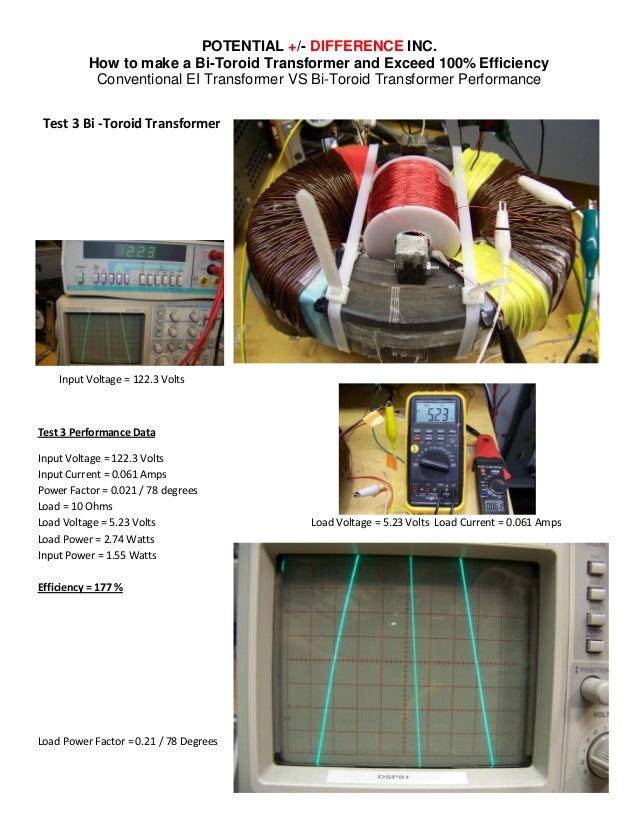
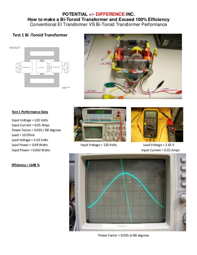
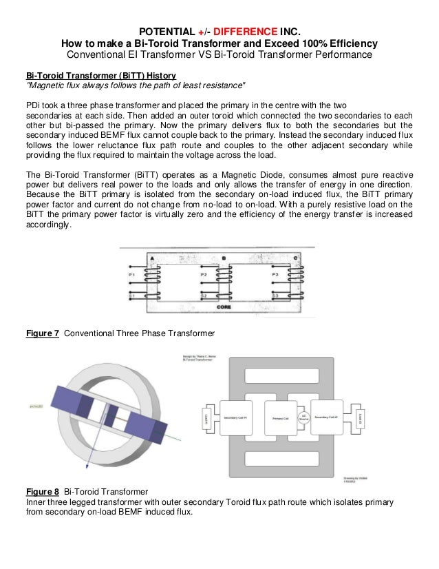
    How to Make a Bi-Toroid Transformer and Exceed 100 % Efficiency

    Have a good day!
    Bob

    Thanks-A-Mill Bob. No I have never read this. Gonna do it now awesome.

    It's High Times

    Mike

    Leave a comment:


  • Bob Smith
    replied
    Mike
    Have you seen all these slideshare presentations (you can select them from right column)
    Pdi Ceo Thane Heins 3240 Connections presentations | SlideShare

    This one might speak more directly to your questions:
    How to Make a Bi-Toroid Transformer and Exceed 100 % Efficiency

    Have a good day!
    Bob

    Leave a comment:


  • BroMikey
    replied
    Keep Trying it

    Hi Dave thanks for the reply, That hat kills me everytime I lived in and near Houston TX

    The information would be much appreciated. I have watched many video's using toroidal cores, square cores, all types and even the one's Clean has shown.

    Yes core material as well as geometry, mass, proportion must play a part in excess production. Consider the Thane original core. It has a heavily built square outer portion with two smaller inter core path of less mass, much less mass.

    This material needs to be able to operate as we all know at the designed cycles or pulses to help with the transfer. And because with a malfunctioning core at the wrong cycling ranges inefficiency rules the equation.

    So we haven't thrown out out text books


    I was also looking at another video of Thanes here he uses a large fat outer toroidal core sliced up and put back with a tiny inter bar reaching across it to hold the primary.

    Yes portion is what I noticed.

    Look at the tiny primary in the Auroratek Trans. Look at the 2 huge secondaries. Mass plays a roll here. Look at how much core material is present.

    It seems to me that a large core for the secondaries with a large mass of secondary windings much co-exist with the tiny flux paths using a small mass of copper primary.

    It keeps getting repeated in all of the extra energy work that coils store energy so more mass should work better.

    Also these large secondaries send the power that is stored in them back and forth through the load, or they resonate.

    Transformers love AC and this is why Bill uses AC at 3200 hertz. Well the frequency will vary from mass to mass and winding to winding.


    Just grabbing some core material and trying it will render something but I think we underestimate Thane.

    The core dimensions with it's mass and geometry is what Thane found good results using and I feel to get 500 percent, needs to be followed.

    Looking close at the core in his video the material is tape.

    Thane spent a great deal of time to find the right portions and geometry using transformer tape with the right metals embedded to correspond to the general frequency ranges for his designs.

    This transformer tape can be ordered for winding cores at home. Well maybe it just looks like tape and one of his videos tells us what his material is, I don't know that. I think his toroidal unit is an off the shelf material but remember how big the outer is holding massive secondaries.

    Mike

    Leave a comment:


  • Web000x
    replied
    I have built a couple of bitoroids. Unfortunately I have no great claims for anybody. Both of mine were not in excess of 100%. It would seem that core material might be a strong factor or that I was not operating at the correct frequency for optimal performance. You must also consider how much magnetizing force you are injecting into the cores. A systematic study of signal frequency and amplitude while plotting the efficiency curves is really what needs to be done to find a sweet spot if there is one.

    I had high hopes for my current setup because of a stash of cores that I had. They are specifically designed for magamps. The BH curve is pretty square. I arranged them in a fashion similar to the AuroraTek demonstration. The turns ratio was in a golden ratio proportioning just for good measure, Primary = 1, Secondary = Phi.

    I can honestly say that this particular setup acts no different than a conventional transformer. I even verified this by taking another one of these magamp cores that I had already wound in a conventional style and compared the reactive power between it and the Bitt style transformer. Both behaved the same.

    I took power measurements on the primary and found something which is food for thought in your endeavors. When using a purely capacitive or inductive load on the secondaries, the primary power is totally reactive. This is in accord with conventional logic.

    Also, when using an LC tank circuit with an associated load resistance, Resonance causes the power factor of the bitoroid primary to equal 1, no reactive power. This, also, in accord with convention.

    The question is: What is it that is causing this novel effect shown by Thane Heins or AuroraTek? Core BH Curve? Reactive power coupled with moderate load resistance on secondaries? Turns ratio between primary and sec?

    I'll post a picture of my setup tomorrow and maybe a few schematics and details I've tried. If you start thinking of replicating, I encourage you to proportion using the golden ratio wherever feasible. I think that is our magic answer for a lot of this 'free energy' tech.

    Dave

    Leave a comment:


  • BroMikey
    replied
    Clean in Canada

    Hey Clean from Canada

    I grew up across the street in Detroit. Been goin down to the river every year to se the Blue Angels Jet fighters.

    Anyway I went through this thread video's and watched you work and I just have to stop and say thanks 4 putting this stuff out in the open. I have learned from you.

    All of us northerners sound like we have a constant head cold that's me


    The BiTT study is a good one and I see you finally cracked this thing wide open. The one thing I thought I had right was the pulse DC but I see the AC is used in BiTT work.

    This must be the Zero crossing circuit you built.

    I can't stress enough how glad I was to be able to watch you and Thane go through these demonstrations.

    You are one of the good leaders here as you don't just talk about what you know but show what it is you mean. There is a vast difference. So many speak about setups and what they mean is unclear unless a demo is shown.

    There just to many variables in these experiments to try to follow without a movie to see the actual work.

    You are moving fast to the level of a white coat high paid inventor, great persistence .

    Mike

    Leave a comment:


  • Hrothgar
    replied
    Sorry bro

    I'm a thinker more than a doer and that makes me a poorer human being than most I simply have not built a bitt But I see clearly the basics of why it works. I tried to build a obtuse fusion of a meg and a transformer but I rushed it and ruined my big ass coil. I'm going to spend time learning the basics first had after I finish paying off child support in about 4 years. When I have more time less work and a lot more discipline.

    Leave a comment:


  • BroMikey
    replied
    Bitt

    Hey Hrothgar

    Did you ever build a successful BITT? If yes, tell me NOW what to do. I am fed up to here with all of the empty chatter all over the web with the might be's could be should bee's

    I need another speriment But I am unwilling to leave it to chance.

    To me you sound like someone to follow. Like when I followed John Bedini's diagrams.

    I want a simple experiment to prove to myself that the BITT can work for me even just a little.

    I can wind coils. I have 20awg wire, 23awg , 25 awg and some 30-40awg wire as well.

    I have the capability to use this oven cured 2 part epoxy I have over here so as to fill a form such a thin round or square metal tube with black sand and or whatever.

    I have ferrite beads. I have some 2,3" E-Cores like found on a Television chassis for high frequency operation.

    What I prefer is a basis test so I can do the more involved prototype.

    If you can help me to select an initial experiment we can leave the hypothetical and veer into the realm of application.

    I was going to and probably still will get my magnets out and show my son a 2 coil iron core trans working without a battery.

    We home school our cridders in our old age this time around


    Mike

    Leave a comment:


  • Hrothgar
    replied
    The bitt is different

    The bitt doesn't work on zero sum. It works on the basis that the primary doesn't allow for the bemf to come back to the primary. so the Bemf gets deflected bouncing between the two secondaries like a pinball. It is an Asymmetric system it gains power by staying out of balance.

    If you build a bitt with all identical cores then it acts like a normal transformer P(+1-1)=S1(+.5-.5)+s2(+.5-.5)

    the real bitt works by not letting the -1 come back from where the .5s reside. keep in mind this is in NO WAY real math the plus and minus signs merely denote separation of charge no actual polarity is implied this is just a crude visualization.
    Last edited by Hrothgar; 09-11-2014, 09:41 PM.

    Leave a comment:


  • Hrothgar
    replied
    Zero sum

    Zero sum is the base concept that an equal amount of flux exits the magnet as enters it. Just like if a 10 gallons of water goes into a water pump 10 gallons comes out. so if the two magnets are balanced and feeding each other then an outside source becomes available to magnet one then magnet two that was feeding magnet one has to find an alternate route for the flux that it was feeding magnet one.
    Last edited by Hrothgar; 09-11-2014, 02:46 AM. Reason: smiley

    Leave a comment:


  • BroMikey
    replied
    Woe Dude Heavy

    Hey Hrothgar that is a good thing to say to me. It takes me time to understand simple things and it's all because it ain't really all that simple.

    But then you don't hear talk like that giving the broader view of motor designs as a collective. So a flux switch sound pretty good to me.

    It reminds me of Jim Murray's switched reluctance thought.

    Hrothgar wrote:
    "we get power from the change as the magnets routing self adjusts to input and bemf "


    That is a good way of summing up where the extra comes from, I would have never thought of that.


    Hrothgar wrote:
    Its about zero sum and change


    Zero sum? You mean like using series wound bifilar coils to neutralize self induction? And it's not just chump change so change without self inductive losses!!! Think this maybe correct, I still am very green, maybe i should listen for awhile.

    This stuff sounds pretty good to me, I ain't it like that before.

    Say on my friend say on. If I use a bi-toroid I should have 2 secondaries wound in opposition to each to cancel to a zero? IS that right?

    I see these Bitt and they don't all show how the windings are hooked up to each other but I think that it might be ??

    Hrothgar wrote:
    Lay multiple paths correctly the Magnets will be isolated from the coils when not firing


    It does seem like you could be talking about a Bitt. I can only focus on one thing at a time. Is it a Bitt you are talking about?

    Good Day Sir.

    Mike

    Leave a comment:


  • Hrothgar
    replied
    Sweeet

    Its about zero sum and change. A permanent magnet has a conceptual fixed field in that if a specific measure of flux leaves that same measure must come back. inserted into a core the flow goes in one direction where as in a coil the flow goes in two directions on a core. Lay multiple paths correctly the Magnets will be isolated from the coils when not firing. Inserting the magnets into a proper core configuration forces change to maintain symmetry because of the zero sum in the magnet pair. In this way we don't get power from the magnets we get power from the change as the magnets routing self adjusts to input and bemf keeping them at zero sum. Put another way when you feed one magnet the other magnet has to find another path to send the flow of flux you interrupted in this way you can form a flux based switch.

    The bitt gains power in that it takes advantage of the increased resistance to backlash on the primary to promote an asymmetric system. Which mathematicians hate more than wedges.

    Leave a comment:


  • BroMikey
    replied
    Puddering Is Kool

    Hello Hrothgar

    Thanks for your reply. I did collect my thoughts yesterday and realized that I have been thinking transformer + Pulsed DC but the Aururatek is JUST AC ONLY.


    I think this is the one wild card out here that many experimenter gave gotten use to pulsed DC and forget to look at the absolute need for ac if specified.


    You see my mind has been on the demo Bill gave using a signal generator going to and AMPLIFIER. This produces a standard AC sine wave but allows adjustment of frequency.

    Very important. I don't mean to be side stepping you specific entry but am needing more time to look at your statements. In other works "Keep Talking" and more we talk about it the better I will get at know what to do.


    Pulsed DC is the most often used supply power and is a great form yet Tesla used AC as well.

    If you have had time to look at the Auroratek video, maybe you could throw a comment my way.

    Bee-C-in Ya-Round

    Mike

    Leave a comment:


  • Hrothgar
    replied
    Pulsed DC only

    Originally posted by BroMikey View Post
    In this video a magnet is used with a transformer to supplement energy.


    Magnet Transformer (free energy) - YouTube


    mike
    That particular setup wouldn't work with AC you need a different core setup to route it to work with AC. also you have to increase you input resistance or you just end up saturating the core like in a magamp which just "opens up the throttle" instead of leveraging extra power from the magnets.

    Disclaimer: That is my own theory I've developed by modelling my own ideas and by what I am currently piddling around with as such I am not an authority by any stretch of the imagination.
    Last edited by Hrothgar; 09-09-2014, 03:05 PM. Reason: Disclaimer

    Leave a comment:

Working...
X