If this is your first visit, be sure to
check out the FAQ by clicking the
link above. You may have to register
before you can post: click the register link above to proceed. To start viewing messages,
select the forum that you want to visit from the selection below.
Here is a poor man who has been attacked for years because of his simple demos but he just keeps coming up with new designs that should not work but do.
While I don't want to rain on anyone's parade, Line transformers aren't the place to put these. I think the best place for these transformers is to integrate them into isolation transformers for modern home electronics to make them near zero or even negative impact devices. It would be easier to sell just don't tell them that its that efficient .
Hello Hrothgar
I see what you mean when I thought about it more and that is why Jim and Paul are working on the SERPS.
The other thought that came to me was figuring out a way to convert it all back and forth. In other words the experiment requires that the AC Line transformer energy coming off of the pole in the yard be converted to a rectified high frequency pulse dc for use, why not just use 100X less from the line?
I think you are talking about returning it to the grid? That is something I have not figured out. But I want one on my refrigerator, all my window AC units, My electric clothes dryer and so on.
I see what you mean though about it being easier to set one of these up for a single device because of the need to tune the load to the transformer.
It probably would not work as well with many home devices going on and off throwing out the tuning.
The way Bill has the demo setup to be used as a heater is very appealing, run a 4000 watt heater for $1 per week.
While I don't want to rain on anyone's parade, Line transformers aren't the place to put these. I think the best place for these transformers is to integrate them into isolation transformers for modern home electronics to make them near zero or even negative impact devices. It would be easier to sell just don't tell them that its that efficient .
Hey Mike
Nice post. Sure drew a lot of detractors when it went up on another forum .
I took down what Bill Alek said about the transformer (in the video) and added a quote from Stupify12 about swbifi winding:
Regards,
Bob
Edit: People really attacked Alek's measurements; maybe they weren't done perfectly, maybe not well at all. However, I still think the principles he outlines in the transformer are worthy of consideration. I do want to try this with 3 ferrite toroids I have.
Thanks for posting Bob
I gotta say you have to be bullet proof so to speak on these forms because people WANT to live in denial. To agree that it might be THAT simple would mean an insult to their pride and all of the money they have spent going no where to find the keys.
We have all been told that it is simple to get the extra. Tesla wore a loin clothe compared to our technology and he could set up a lunch box size device and split the earth.
Today with all of our fancy EE topology we freak out if our little experiments go to 100 percent.
Thanks again for posting what Bill had said in the video.
Bill did alright by me with his figures. He did the conventional transformer first the same way and the results were different.
Why can't people just acknowledge that Bill is showing something that is not a normal phenomena.
For pete sakes he did everything the same in both experiments.
10vdc input at said freaks and the output was more using the BI-Toroidal, whats the big deal? It is well know that Bi-Toroidal Transformers offer better results than closed system designs.
Let's just say that this one process of extracting energy from the earth's Dyno is ridiculously easy. Don't these detractor think that there is enough electrical current to be had to go around like Tesla said???
Look at the mass comparison of both secondaries VS. the tiny primary wind.
We need to get down into this work with the Bi-Toroids using something other than coat hanger wire for cores. I bought some magnetite some time back to mix into my paint to make a magnetic chalk board replacement for the children to stick magnet letters on.
The iron dust called magnetite was not expensive. A few bucks worth of large neo's to align particulate while curing takes a hold and I can have any shape I want like Bill Mullier did.
I am telling you that is a lot of mass for the secondaries, I just can't get over that. We need to look at that mans transformer and put our hand over our mouths for a while before we speak.
Can you imagine how big a Bi-toroidal transformer would need to be using the transformer in the video as a standard for conversion?
Where are all of my Engineers who flex all of their mathematical muscles ranting free energy detractions? Figure that one out gentlemen.
Bill is only getting a couple-a-watts out of that Bi-toroid, so it ain't so free when you look at what the price is going to be to just run a 100 watts.
We all know how these experiments work well on one watt of energy. The efficiency figures look so much different for running larger amounts of practical power levels.
But if we get 2X or 3X that is still pretty good and not considered an O.U. device till it reaches over 4X by the Patent Office.
That's because the Patent Office a great many devices listed at 2X,3X O.U. even a Mosfet is an O.U device.
What's the big tute? I'll tell you what it is. Pride. That's all it is. We are all wired up the same, men are made like that. You see how patient Bill was with 4-5 people talking over top of him while he delivers his heart to the world?
You see that? Bill is a great man.
Bill has tried to explain all of this before, you can tell by the way he throws out the punch line and no body gets it. Yet he still remained calm, I got to hand it to him for his kind persistence.
Each time the results were offered no one in the room had the math skills to see his claim.
Where are you Farmhand? Where are you now? How are you going to say this man is deceiving himself this time?
I know who you mean Bob there are a bunch of them.
I guess I have not been skeptical enough at times in my life and I believe others easily then when the claim turns out false, I look like a fool. Oh yeah I have looked a fool many many times for that.
I am well exercised at being embarrassed. Yeah I still believe it is possible when I look a fool ahuh.
Hey Mike
Nice post. Sure drew a lot of detractors when it went up on another forum .
I took down what Bill Alek said about the transformer (in the video) and added a quote from Stupify12 about swbifi winding:
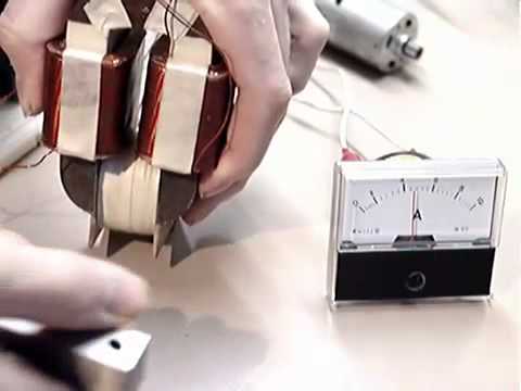
"The general geometry of this transformer is very different than a traditional transformer, because what we have is a primary coil wrapped around two cores. And really, we have that same type of architecture in a standard transformer...'cause what you do in a standard transformer is that you have the material going down the centre of this coil. So really, you're splitting the flux two ways, and that's what we're doing here - splitting the input flux two ways."
"The difference is that we have these two output coils that are wired in such a way that it has a bifilar configuration. ... where the output sets up opposing magnetic forces into this [secondary core] material... There's two configurations available [for the secondary]... You can wire the output in series or in parallel; in this case they're wired in series... the ratio ...is about 20 turns here [primary] and 120 turns for each secondary. So we're actually stepping up the voltage. ... They're just single wound [secondary] coils set up in an opposing configuration."
"And what that does to the behaviouur of these coils is that they lower the natural impedance on these cores, driving it overunity, where normally, you wouldn't see that on an output coil here. ...You'd see a fixed output impedance on the secondary here. But when this operates, the behavior is quite different because we have this cancellation going on, lowering the impedance on this [secondary] coils."
In response to a question about the opposing wound secondary coils, he calls this " a key feature with building overunity devices, because we're lowering the impedance on these coils. ... There's something going on; another force involved."
Some notes:
- running the transformer at 3200 cycles per second for best performance
- input side highly reactive compared to regular transformers.
- shorting the output coils shifts the phase angle to 102 deg
More quotes:
"We're dealing with some sort of source that's all around us here, some sort of a negative energy and that's what's pushing this wave form beyond 90 degrees. there's another force at play here; this other force acts like a negative electromagnetic force; that's what's acting on the current, pushing it beyond 90 degrees."
Quote from Stupify12
I have build the same Bifilar coil into a Tesla Transformer- air core, The effects me and my cousin have seen is when there is load on the secondary coils the Transformer seems to boost its performance and not affected in the so called counter induction. So we tried to add more coils in the Transformer, we have accidentally stumble on it the other secondary is powering a load of bulb with full brightness, accidentally Short circuit the new other Secondary coils that result into a boost of brightness on the bulb being load on the other secondary.
We have tried to make more shorted Bifilar secondary coils on this Transformer it seems to boost its performance with out demanding more power from the input source.
Source: Tesla's "COIL FOR ELECTRO-MAGNETS".
Regards,
Bob
Edit: People really attacked Alek's measurements; maybe they weren't done perfectly, maybe not well at all. However, I still think the principles he outlines in the transformer are worthy of consideration. I do want to try this with 3 ferrite toroids I have.
Last edited by Bob Smith; 09-07-2014, 07:39 PM.
Reason: Adding further comment
This method was developed by the late Bill Muller for his motors. Make a frame or mold of the exact size of magnetite core you wish to cast, and line it with a material that will allow you to get the core out after it sets up. Make sure the end plates are made of .125 inch plastic sheet. Mix your magnetite with a slow curing, high temperature resin. Mix as much magnetite into the resin as possible while it is still malleable. Fill the mold and place the end plates on each end, and then place a strong, NEO magnet on EACH SIDE of the mold. The NEO magnets should be at least as large as the magnetite core you are making, and should face each other in the attraction mode, so that all of the particles of magnetite line up, and TOUCH EACH OTHER as the resin sets. This also aligns the magnetic domains in the iron so they are all parallel in the finished core.
Any other method yields very poor results.
When the resin is set (24 hours), the magnetite disc should be able to magnetize up to at least 2500 Gauss and operate with a very narrow hysteresis curve. It will be a complete "non-conductor" so "eddy-currents" will be very low.
Bill Muller used these cores in his motors as a cheap substitute for Metglas Cores. They have many of the same high-speed switching characteristics, but their magnetic permeability is much lower.
I am glad to hear that you are getting and iron core just the way you want it. However metglass it something else and offers a better response at the higher frequencies. As far as I know black sand can be molded using quick set epoxy from the hardware, into any size and shape for pennies.
The iron laminate is a very slow core material, although it may work some.
Was there a reason you decided to leave the metglass design? Maybe metglass is expensive? I have never priced that stuff.
Mike
I suspect Metglas is pricey and a bit hard to find unless we order in volume. I'm interested in knowing if the material matters or if the concept is universal.
This variation of the Thane Heins transformer uses multiple cores with winding around pairs of cores instead of windings around a single custom core.
I'll be very pleased if this indeed work the same way, because I went through hell and back trying to get a custom core made using silicon steel laminates--it's doable but you will pay dearly to get someone to make them for you as prototypes.
Hi Dog-One
I am glad to hear that you are getting and iron core just the way you want it. However metglass it something else and offers a better response at the higher frequencies. As far as I know black sand can be molded using quick set epoxy from the hardware, into any size and shape for pennies.
The iron laminate is a very slow core material, although it may work some.
Was there a reason you decided to leave the metglass design? Maybe metglass is expensive? I have never priced that stuff.



 .
.


Leave a comment: