Announcement

Collapse
No announcement yet.

Bi-toroid Transformer of Thane C. Heins

Collapse
X
 
  • Filter
  • Time
  • Show
Clear All
new posts

  • BroMikey
    replied
    Unsure of HV Explosions

    "They sort of snap like a fire cracker dem critters"

    This is what I have heard of and other guys warn about in their video's so no I don't know what I am doing half the time, that way I get more excitement in my life but folks really should take care of their eyes.

    Thanks Web000x I am still learning.

    All day I handle 220vac and I respect electricity believe you me. Some of my electronic ignition gas stoves will set you too, but nothin like the time I was sweating like a drill Sargent working on a Television 20 years ago, bumped the flyback with a wet elbow. Now THAT is excitement I can do without.

    I was all tired out working into the night and THAT ended MY day right there.

    Now let me say that I feel bad that you had to repeat that you used HV caps in another post. I don't know how I missed that. I see so many videos and read so many posts that sometimes any one subject gets rolled under.

    It is important to repeat and for this i am glad that you took the time.

    I think Mr Clean says that in his videos too, but I figured it out by realizing I don't have any cap that even came close to the size Clean has in his video's.

    One thing tuning requires is and number of caps to add together say in increments 20's and 10's then 1's and .1's so that a fine line can be arrived at without using a variable capacitor with a gear reduction box.

    It is a fine line. Even though you can not excess the full resonance I suppose because of the high frequencies needed, many harmonics exist in between that if tuned give peak results.

    The only circuit I have tuned using a cap is an AM&FM RADIO so this will be a new experience.

    I think the 2000volt disk caps are the big ones but I really don't know what I will find. Any suggestions would be welcome. I generally look on EBAY.

    The bigger the winding the higher the voltage so caps need to be able to perform their task without running the red-line.

    Besides the stink I hate blowing up any part as this may short and damage other components in a circuit.

    So the good thing is that my mind is fixed properly on the safety issues.

    Mike


    Originally posted by Web000x View Post
    Yes, like I stated in a couple of posts, you must use HV rated caps. I am easily seeing 500 Volt cap voltages close to resonance, this with never more than 26 volts input. I don't operate in full resonance so I don't even get close to what the full potential of resonance may be. I do use a neon bulb and a 10 megohm resistor across my caps so that I have some visual indication to be safe. Please be careful. If you are unsure of what you are doing, shield your caps with something like a shoebox so they don't put your eye out when they explode.

    Dave
    Last edited by BroMikey; 10-10-2014, 06:46 AM.

    Leave a comment:


  • Web000x
    replied
    Originally posted by BroMikey View Post
    Hey Dave Ozone production requires super high voltages doesn't it? You are not running kilovolts, I didn't think. Maybe that is why HV caps work better for tuning?

    Mike
    Yes, like I stated in a couple of posts, you must use HV rated caps. I am easily seeing 500 Volt cap voltages close to resonance, this with never more than 26 volts input. I don't operate in full resonance so I don't even get close to what the full potential of resonance may be. I do use a neon bulb and a 10 megohm resistor across my caps so that I have some visual indication to be safe. Please be careful. If you are unsure of what you are doing, shield your caps with something like a shoebox so they don't put your eye out when they explode.

    Dave

    Leave a comment:


  • BroMikey
    replied
    Russian Bi-Toroid 2009

    Here is a Bi-Toroid array that they call OVER UNITY TRANSFORMER and clearly can be compared with any twin coil dual secondary design.


    Russian overunity transformer - YouTube


    This is a 3Phase version using twin triple phase specialized transformers. One is larger than the other and work together to regenerate energy that normally is lost.

    This is pre-2009


    Mike

    Leave a comment:


  • BroMikey
    replied
    Ozone

    Originally posted by Web000x View Post
    Update: I just removed 14 turns from my primary on my SFT2 and ran some preliminary experiments with power calculations. This seems to be the way to go. I get a much broader frequency range of negative power factors and a more robust heat dissipation in the output. I'd love to run this thing into full resonance but my coils start hissing and smell like ozone. Follow Bill's lead with the tiny primary and big secondaries.

    Added Update: My circuits are always very much less efficient when I DON'T have capacitance in the secondary circuit. Without capacitance, it acts totally conventional. Sounds like series wound bifilar for the added capacitance is my next step.


    Dave
    Hey Dave Ozone production requires super high voltages doesn't it? You are not running kilovolts, I didn't think. Maybe that is why HV caps work better for tuning?

    Mike

    Leave a comment:


  • BroMikey
    replied
    On The Road Again

    You are back on the road again it seems. You are right I would say to follow bills lead, he has saved me years of work already. Dug out my systron-donner genny today looks sweet on the scope for a poor boy like me. I got it for less than $100.

    It is the 106A Datapulse lets me delay if I want leading edge trailing edge, pulse width and much more so the only question I have is WHY DOES IT SAY 10v input tops? Maybe I need to use a resistor on the triggers anyway.

    I will figure it out.

    Sounds like you hit another ball out of the park. Yes Bills ratio make sense because I used a 1:1 ration for kicks and at 27volt input all I got out was 8volts at 60hz.

    Course the picture changes with high frequency however the ratio Bill is using it 3:1 I believe. 40 turns and 120turns I think.

    Keep doing your tests, I can't think of a better techy to hammer this stuff out, I mean after all you are an electronix master for the most part.

    Why not go ahead an surprise the academics who think that there is no way to tap into the earths dyno.

    I can hardly wait till Dog-One slams those huge core up on the table with a decent set of windings. But either way if the system can run on it's own LEDs prove the point just as well.

    Tuning with caps is important and I don't know why Mr Cleans caps that are disk shaped looks so big, is this because they have a higher voltage rating? I mean I have some itty bitty caps the size of a pin head but I think he is using caps rated at 2000 volts. Not sure why they are so giant. But it must be for a reason.

    I'll tell you this, caps have always been a wild card in all circuits. Look at how many different kinds that there are.

    The primary is an exciter like Dog-One stated so this means it uses a few windings to get the process of reflected power between secondaries.

    Another thought is using core material with a lower value for the primary to secondaryS LINKS. Or just make the links smaller. I don't know but this is the right way to view this project.

    Whats wrong with a little Ozone? we can't have it smoking now can we?

    Super progress.

    I finished up on my spool for the secondaries also. Then one more for the primary. My secondaries are coming out at around 160-170 turns so I was thinking a 60 turn primary but I may drop to 50 turns now. But hey guys lets not forget the mass of those secondaries. The primary must be 2 gauges smaller AND 3 times less on the length of wire, think about it.

    I did a quick triangular test winging out of some old 10awg wire I had to see how it fits. Perfect fit so I am ready. I still am looking for 2 more cores for a total of 7 flyback cores. They are here some where

    Mike


    Originally posted by Web000x View Post
    Update: I just removed 14 turns from my primary on my SFT2 and ran some preliminary experiments with power calculations. This seems to be the way to go. I get a much broader frequency range of negative power factors and a more robust heat dissipation in the output. I'd love to run this thing into full resonance but my coils start hissing and smell like ozone. Follow Bill's lead with the tiny primary and big secondaries.

    Added Update: My circuits are always very much less efficient when I DON'T have capacitance in the secondary circuit. Without capacitance, it acts totally conventional. Sounds like series wound bifilar for the added capacitance is my next step.


    Dave
    Last edited by BroMikey; 10-09-2014, 08:12 AM.

    Leave a comment:


  • Web000x
    replied
    Update: I just removed 14 turns from my primary on my SFT2 and ran some preliminary experiments with power calculations. This seems to be the way to go. I get a much broader frequency range of negative power factors and a more robust heat dissipation in the output. I'd love to run this thing into full resonance but my coils start hissing and smell like ozone. Follow Bill's lead with the tiny primary and big secondaries.

    Added Update: My circuits are always very much less efficient when I DON'T have capacitance in the secondary circuit. Without capacitance, it acts totally conventional. Sounds like series wound bifilar for the added capacitance is my next step.


    Dave
    Last edited by Web000x; 10-09-2014, 05:42 AM.

    Leave a comment:


  • Dog-One
    replied
    AlphaCores

    Haven't received my FerroXCube cores yet, but i did get my AlphaCores, so I figured I'd run a few preliminary tests. I wrapped my primary winding and ran a frequency sweep. These cores appear to transfer power at frequency unlike the silicon steel ones. They also idle nicely at 90 degrees when you have no load. So far this looks to be a real good starting point. When I figure out what type of wire to use, I'll get some secondaries wrapped and see what this SFT replica is capable of.
    Attached Files

    Leave a comment:


  • Web000x
    replied
    Originally posted by BroMikey View Post
    Hey Web000x

    Did you see Mr Clean's BiTT when he hit a node? The BiTT self resonated and Clean could unhook the battery and it would continue to run on. Did you see it?

    I think it is just as important to tuning with scopes as tuning the other way. Tuning till you can run something after the battery is unhooked is my thought.

    If you can not recycle any of the resonant energy so that the load runs on after unhooking from the battery, you will always be on the short end.

    There are more ways than one to tune.

    What Mr Clean showed us is not a joke. Clean uses caps for tuning yes just like he learned from the Don Smith information. He sent some energy from the load BACK to the primary THROUGH a resistor. The resistor is used to limit how much he sends back so as not to drain completely the 2 secondary coils AND IT RUNS ONE AND ON.

    Just like Lasersaber did with his looper.

    Just like akula does with his stuff.

    Web000x hey? When you run this BiTT does the amp draw rise on the primary when you short out the load?

    No it shouldn't so is that the same as a conventional transformer?

    Okay watch this.

    I took my two coils that you heard I wound and hooked them together different ways. The first time I used a single core and when I shorted the secondary the primary did not rise.

    However as I continued to hook more coupling core materials the primary would go up.

    Then I put the small primary inside the large secondary and the amps tripled on shorting.

    The coupling PROPORTION is very important just as much as so many other factors such as primary to secondary ratio/frequency/voltage/!!!

    Start here https://www.youtube.com/watch?v=BTPm4pBipfY

    I think these BiTT need to be large enough to display even a small effect or shall I put it another way. Look at all of that transformer Bill has on the bench and look at his power levels.

    Bill runs at very low power so compared to your size BiTT you need to run 5ma and try to power a 1 watt led to see when it brightens up.

    These are only suggestions that is my understanding of what I observe from others. Your BiTT is capable of running a single LED without the battery connected AFTER resonance is hit or whatever tuning node if you want to look at it that way.

    https://www.youtube.com/watch?v=UNmj8nJyuuY

    You have made a step in the right direction by throwing out your iron cores but don't quit your day job as tuning may take more effort than throwing together a few cores and magwire coils.
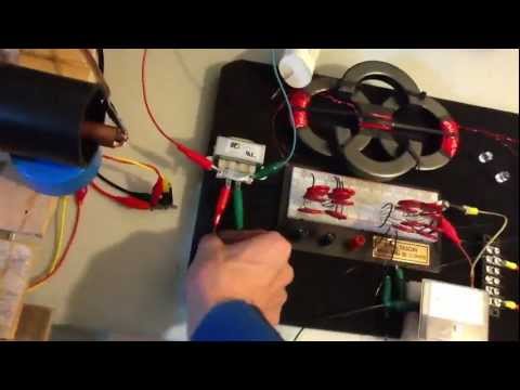
    We are randomly making BiTT windings with whatever core we think is in the frequency range, coils are wound like like a clown pulls a rabbit out of a hat, so this is just a sort of ball park lottery dreaming so far to get our feet wet.

    Hang in there.

    Mike
    Mike,

    I would love to see Mr. Clean unhook his circuit from his battery and have the thing continue to run. Please post a link to that.

    Yes, the amp draw on the primary does go up when I short my coils, just like a conventional transformer.

    As far as I can tell, Mr. Clean has showed nothing that I would call a 'solid' measurement of power. All of his observations are qualitative, with very little attention to phase angles. Phase angles can do crazy things when you take them into consideration. For example, if I have 5 volts and 5 amps that I'm measuring. For a phase angle of 0, that is 25 watts; a phase angle of 90, is 0 watts; a phase angle of 180 means the load is providing 25 watts of power that is going back to the source. THIS IS IMPORTANT. You cannot do these studies without showing phase angles. Else, they mean nothing.

    In Mr. Clean's video, 39C Bitoroid For HV Resonant Drive Transformer, Tune and Testing - YouTube, he shows his measurements towards the end. He shows that his output is 35 volts at half an amp. Take a close look at his scope. Look at the SPIKES that are registering 35 volts. If you count the divisions, it looks like his voltage reading is being taken from peak to peak. This has no relation to RMS whatsoever and is not qualified to use for average power calculations.

    For the record, I have done my homework.

    Dave

    Leave a comment:


  • BroMikey
    replied
    Bi Toroid Tuning

    Here is Mr Clean

    His video gives us an idea how he does his tuning

    Listen to his laugh when he gets OU.

    Thane has forwarded this video to all replicators.

    39C Bitoroid For HV Resonant Drive Transformer, Tune and Testing - YouTube


    Got to do the home work.

    Mike
    Last edited by BroMikey; 10-09-2014, 01:53 AM.

    Leave a comment:


  • BroMikey
    replied
    Bi-Toroid

    Hey Web000x

    Did you see Mr Clean's BiTT when he hit a node? The BiTT self resonated and Clean could unhook the battery and it would continue to run on. Did you see it?

    I think it is just as important to tuning with scopes as tuning the other way. Tuning till you can run something after the battery is unhooked is my thought.

    If you can not recycle any of the resonant energy so that the load runs on after unhooking from the battery, you will always be on the short end.

    There are more ways than one to tune.

    What Mr Clean showed us is not a joke. Clean uses caps for tuning yes just like he learned from the Don Smith information. He sent some energy from the load BACK to the primary THROUGH a resistor. The resistor is used to limit how much he sends back so as not to drain completely the 2 secondary coils AND IT RUNS ONE AND ON.

    Just like Lasersaber did with his looper.

    Just like akula does with his stuff.

    Web000x hey? When you run this BiTT does the amp draw rise on the primary when you short out the load?

    No it shouldn't so is that the same as a conventional transformer?

    Okay watch this.

    I took my two coils that you heard I wound and hooked them together different ways. The first time I used a single core and when I shorted the secondary the primary did not rise.

    However as I continued to hook more coupling core materials the primary would go up.

    Then I put the small primary inside the large secondary and the amps tripled on shorting.

    The coupling PROPORTION is very important just as much as so many other factors such as primary to secondary ratio/frequency/voltage/!!!

    Start here https://www.youtube.com/watch?v=BTPm4pBipfY

    I think these BiTT need to be large enough to display even a small effect or shall I put it another way. Look at all of that transformer Bill has on the bench and look at his power levels.

    Bill runs at very low power so compared to your size BiTT you need to run 5ma and try to power a 1 watt led to see when it brightens up.

    These are only suggestions that is my understanding of what I observe from others. Your BiTT is capable of running a single LED without the battery connected AFTER resonance is hit or whatever tuning node if you want to look at it that way.

    https://www.youtube.com/watch?v=UNmj8nJyuuY

    You have made a step in the right direction by throwing out your iron cores but don't quit your day job as tuning may take more effort than throwing together a few cores and magwire coils.

    We are randomly making BiTT windings with whatever core we think is in the frequency range, coils are wound like like a clown pulls a rabbit out of a hat, so this is just a sort of ball park lottery dreaming so far to get our feet wet.

    Hang in there.

    Mike


    Originally posted by Web000x View Post
    So I've been running both SFTs in a similar configuration to Thane's and Bill's with just the resistive load and no cap. I just want to post some observations that I've hammered out on paper. I've yet to see anything interesting from this transformer while I'm powering a load like this. There always seems to be less than 100% efficiency, impedance matching and coil shorting. It follows conventional transformer laws pretty closely.

    This is what almost caused me to give up on my current SFT. I wasn't seeing anything significant so I got despondent about even trying. Something pushed me back in the lab and after 30 more minutes of tinkering and deciding to connect a series resonating cap, I saw something worth my time.

    These transformers may not be as straight forward as popular opinion might lead you to believe. From my limited observations, core material is going to be what makes or breaks your experiments. This is very important. I cannot replicate what Thane or Bill saw with my setup. But I am able to elicit a negative power factor when I tune correctly. There is some type of BH property that makes this happen. Does anybody know the exact material of Thane's original Bitt or Bill's SFT and could post BH curves of it on the thread?

    Thanks,

    Dave
    Last edited by BroMikey; 10-08-2014, 08:29 AM.

    Leave a comment:


  • Web000x
    replied
    So I've been running both SFTs in a similar configuration to Thane's and Bill's with just the resistive load and no cap. I just want to post some observations that I've hammered out on paper. I've yet to see anything interesting from this transformer while I'm powering a load like this. There always seems to be less than 100% efficiency, impedance matching and coil shorting. It follows conventional transformer laws pretty closely.

    This is what almost caused me to give up on my current SFT. I wasn't seeing anything significant so I got despondent about even trying. Something pushed me back in the lab and after 30 more minutes of tinkering and deciding to connect a series resonating cap, I saw something worth my time.

    These transformers may not be as straight forward as popular opinion might lead you to believe. From my limited observations, core material is going to be what makes or breaks your experiments. This is very important. I cannot replicate what Thane or Bill saw with my setup. But I am able to elicit a negative power factor when I tune correctly. There is some type of BH property that makes this happen. Does anybody know the exact material of Thane's original Bitt or Bill's SFT and could post BH curves of it on the thread?

    Thanks,

    Dave

    Leave a comment:


  • BroMikey
    replied
    Spool is Triangular

    Here is my offering today as I progress in my build. This will be the third coil I have ever wound in my entire lifetime other than those Bedini coils that look more like rope.

    Coil winding can be done as well by pounding nails into plywood but I like my way better. I have just finished my third spool and will wind a coil next chance I get.


    The picture is close but the coil is actually more rounded on all corners.

    Mike (Good night )
    Last edited by BroMikey; 10-08-2014, 06:09 AM.

    Leave a comment:


  • BroMikey
    replied
    Diagram

    Originally posted by Dog-One View Post
    Great info Mike and it confirms my suspicious.

    When you get to it, I'll be real curious what you see at higher frequencies.

    My big silicon steel cores seem to drop out quickly above about 150 Hz. When I say drop out, they no longer pass any current, meaning the magnetic field inside the core simply can't change directions fast enough to keep up with the input frequency.

    Thanks Dog-One for keeping on me with the little suggestions that are all turning out to be right. I have here a diagram and I have thought this through just a little BiTT more.

    The C-core's that each individual purchases must be laid out like this on say a piece of paper to get a better fit to optimize coupling.

    I have measured a BiTT more and am going with this coil pattern.


    Mike
    Last edited by BroMikey; 10-07-2014, 04:42 PM.

    Leave a comment:


  • Dog-One
    replied
    Great info Mike and it confirms my suspicions.

    When you get to it, I'll be real curious what you see at higher frequencies.

    My big silicon steel cores seem to drop out quickly above about 150 Hz. When I say drop out, they no longer pass any current, meaning the magnetic field inside the core simply can't change directions fast enough to keep up with the input frequency.
    Last edited by Dog-One; 10-07-2014, 05:15 PM. Reason: typo

    Leave a comment:


  • BroMikey
    replied
    Single coil test

    I did some tests using 1 primary and 1 secondary.

    First test was a single flyback c-core from primary to sceondary.

    I stopped at 1 amp and the voltage 12.5vac input sec 7vac output

    Test two was to drop some ferrite core material of the same kind down into the empty spaces of the primary.

    No change.

    Next test was to take a ferrite toroidal core and split it (I did this with a chopsaw) then put it around the coil.

    The amp draw dropped to .5amps same approx volts 12.5vac

    Next test I put another c-core on the primary

    Amps drop to .35 amps

    Next test use both c-cores from the primary to the secondary

    Amp drop to .2

    Next I ran the variac back up to 1 amp the voltages is 26vac and sec 8vac output

    In each case I shorted the secondary and the amp draw would climb a little.

    I can see now that I need a double C-core from primary to each secondary.

    One C-core is not a very good tie.

    I will be doing more tests but I am probably going to hang these coils up and turn some triangular shaped coils using the same 4" PVC spool heating it gently to reshape.

    My primary is not quite big enough on the I.D. even with reshaping.

    I see now my error and as small as it is at first glance can be easily over looked. It's okay because I can use all of my coils somewhere.

    The more I look at the Auroratek design the more I SEE that Bill's coils are shaped in a triangle for good reason. This allows for wide C-core links on both sides.

    I will continue to add spool shapes to my winder after proper measurements.

    I have decided to go to 3 thin C-core all together for the link between the secondaries and 2 thin C-cores for each Primary link.

    This is more proportionate to Bill's core material volume.

    To do this i will NEED triangular shaped coils to get the cores in the right place. These coils can not be reshaped and I won't mess them up.

    SO the conclusion is that in order to get the voltage up to 25volts with a 180 foot coil 3 cores must placed around the coil, 2 make a link to the secondary and one small c-toroid to fill in the empty space.

    In each case the core material must encircle the windings.

    So to reach 117vac using this material a coil with 5 times as long as this one.

    This is 180 X 5 = 900 feet.

    These are my first tests and conclusions of the basic experiment as Thane had originally presented it. These tests give any experimenter a relative idea of the differences between conventional iron and ferrite as an alternative core.

    Conventional coils using iron use 5 times less wire in this case. I have 4 or 5 different pump motors with their spools easily recovered form them and in each case these motors use 21 awg, 22awg, 23awg,25awg and 26awg wire.

    In each case these pump motors have a 180 foot length down to about 150 foot for the thinner wire. So we can see that ferrite requires an approx 900 foot section of wire to maintain voltage to the same level.

    This is only significant if a BiTT is to be constructed without the use of elevated oscillations not leaving the 60hz range.

    Mike
    Last edited by BroMikey; 10-07-2014, 08:07 AM.

    Leave a comment:

Working...
X